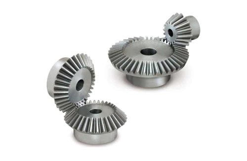
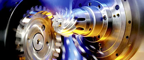
Bevel Gears (European Standard)
As one of the bevel gears manufacturers, suppliers, and exporters of mechanical products, We offer bevel gears and many other products.
Please get in touch with us for details.
Mail:[email protected]
Bevel Gear: The Complete Engineering & Sourcing Guide for Australian Industrial Buyers
Data from Australian manufacturing facilities shows that over 40% of avoidable drivetrain failures stem from incorrect bevel gear selection — a problem that costs the average plant between $10,000 and $60,000 per incident once downtime, emergency freight, and labour are counted. A bevel gear, defined as a gear with teeth cut on a conical surface that transmits power between intersecting or non-parallel shafts, is one of the most versatile and efficient direction-change components available to mechanical engineers. With efficiencies reaching 97–99% in spiral bevel configuration — compared with 60–90% for worm gear alternatives — and applications spanning automotive differentials, industrial reducers, agricultural machinery, and marine drives, selecting the correct bevel gear type and specification from the outset is one of the highest-return engineering decisions in drivetrain design. Australia Ever-Power, at 27 Harley Crescent, Condell Park NSW 2200, supplies ISO-certified bevel gears across all types and sizes with same-week dispatch to Sydney, Melbourne, Brisbane, Adelaide, and Perth.

What Is a Bevel Gear?
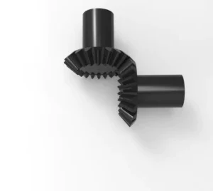
A bevel gear is a gear whose teeth are cut on a conical surface, enabling it to transmit rotational motion and torque between two shafts whose centrelines intersect at an angle — most commonly 90°, though designs from 45° to 135° are achievable.
Unlike spur or helical gears, which operate between parallel shafts on flat cylindrical surfaces, bevel gears use the pitch cone geometry to redirect power around corners in a drivetrain, making them indispensable wherever a shaft's rotation direction must change without the use of chain drives, belt drives, or universal joints.
The defining feature of bevel gear geometry is the pitch cone: each gear in a mating pair is machined on a conical blank, with the imaginary cone apex meeting at the shaft intersection point. When teeth mesh along this shared cone surface, rotational force transfers smoothly from the driving shaft (pinion) to the driven shaft (crown gear), with load carried across the tooth face width rather than concentrated at a single point.
According to ISO 23509:2006 (Bevel and Hypoid Gear Geometry) and AGMA 2003-C10 (Rating the Pitting Resistance and Bending Strength of Generated Bevel Gear Teeth), bevel gears are classified by tooth form (straight, spiral, zerol, hypoid), module, pitch cone angle, and accuracy grade. In Australia, machinery containing bevel gears must meet AS 4024.1 (Safety of Machinery) for guarding and risk assessment, and gear geometry documentation must reference AS 2938 (Gears — General).
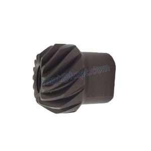
The working principle is straightforward: as the driving gear rotates, its conical teeth engage the mating gear's teeth along the shared pitch line. For straight bevel gears, engagement is abrupt — all tooth contact occurs simultaneously across the face width. For spiral bevel gears, curved teeth engage progressively from one end of the face to the other, distributing load across multiple teeth simultaneously and producing smoother, quieter operation. This progressive engagement is why spiral bevel gears deliver 25–35% more load capacity per unit size than straight bevel equivalents of the same module.
Bevel gears are found in virtually every sector of Australian industry — from the automotive differentials rolling off Melbourne's assembly lines to the harvester PTO drives servicing South Australia's grain belt, the marine propulsion gearboxes working Brisbane's waterways, and the mining conveyor drives running continuously in Western Australia's Pilbara. Their combination of high efficiency, compact envelope, and design versatility makes them the standard solution for angular power transmission wherever performance and reliability are non-negotiable.
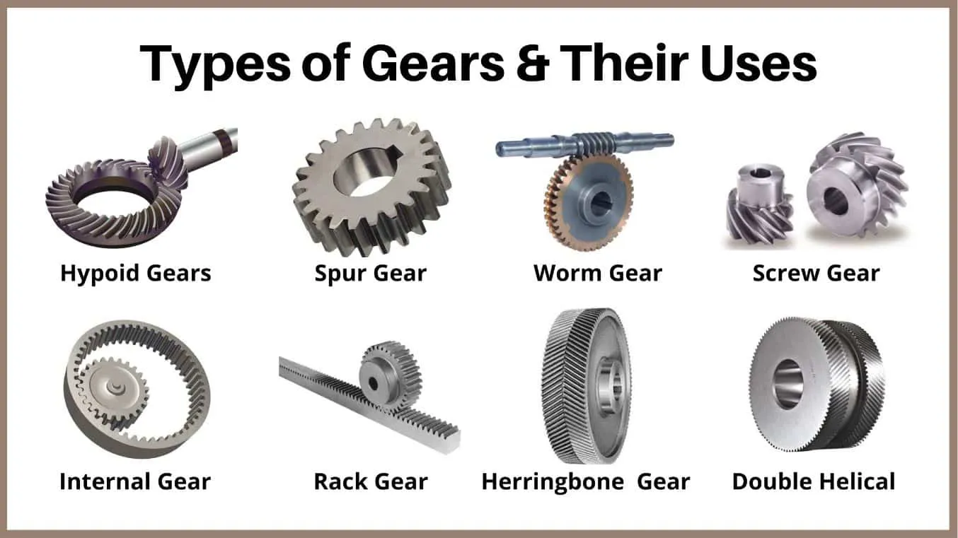
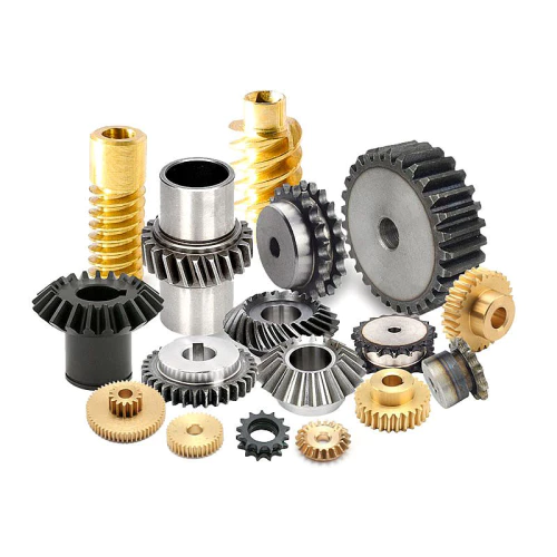
Types of Bevel Gears: Configurations, Ratios & Tooth Forms
Bevel gears are available in four principal tooth forms and two standard configuration types — Type A and Type B — with standard gear ratios from 1:1 through 1:4 covering the majority of industrial applications.
Understanding the distinction between configurations and tooth forms is the first step to correct specification.
Configuration Types
| Configuration | Available Ratios | Hub Style | Typical Use |
|---|---|---|---|
| Type A | 1:1, 1:2, 1:3, 1:4 | Standard plain bore | General industrial drives, instruments, conveyors |
| Type B | 1:1, 1:2, 1:3, 1:4 | Extended hub / flanged | Machine tools, agricultural drives, power tools |
Tooth Form Comparison
| Tooth Form | Speed Range | Load Capacity | Noise Level | Efficiency | Best For |
|---|---|---|---|---|---|
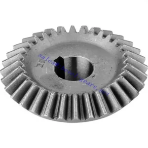
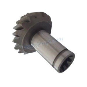
| Straight Bevel | <1,500 rpm | Medium | Moderate | 95–97% | Slow drives, agricultural machinery, instruments |
| Spiral Bevel | Up to 8,000 rpm | High (+25–35%) | Low (−8 to −15 dB) | 97–99% | Automotive, aerospace, robotics, CNC drives |
| Zerol Bevel | Up to 3,500 rpm | Medium–High | Low–Moderate | 96–98% | Medical devices, printing presses, oil machinery |
| Hypoid | High (offset axes) | Very High | Very Low | 94–97% | Automotive differentials, heavy trucks, marine |
Straight bevel gears are the simplest and most cost-effective tooth form, suitable for low-to-medium speed applications where noise is not a primary concern. Their straightforward geometry makes replacement straightforward — a significant advantage for maintenance teams at regional Australian agricultural and construction operations where complex sourcing processes are impractical during peak seasons.
Spiral bevel gears represent the performance standard for Australian industrial drives. Their curved, oblique teeth engage progressively, distributing contact stress across a larger tooth area simultaneously — this is why they deliver 25–35% more load capacity than straight bevel equivalents at the same module, and why they operate 8–15 dB(A) quieter. For Sydney food-processing plants subject to Safe Work Australia's 85 dB(A) noise action levels, or Melbourne robotic assembly lines where precision motion matters, spiral bevel gears are almost always the correct specification.
Hypoid bevel gears differ from the other forms in one important respect: the pinion axis is offset from the crown gear axis, allowing lower floor-profile mounting in automotive axles and enabling very high gear ratios in a single pair. The tooth sliding that results from this offset requires extreme-pressure (EP) hypoid lubricants — standard gear oils are insufficient and will cause accelerated wear within hundreds of hours.
Key Specifications & Parameters for Bevel Gears
Bevel gear datasheets carry more interdependent parameters than most gear types — every parameter affects the others, and a single incorrect value can negate all other correctly specified criteria.
The reference table below covers the full specification range available through Australia Ever-Power for both standard stock and custom-manufactured bevel gears.
| Parameter | Standard Range | Reference Standard |
|---|---|---|
| Module | M0.15 – M20 | ISO 54 preferred series |
| Gear Ratio | 1:1, 1:2, 1:3, 1:4 (standard); custom ratios available | Determined by tooth count |
| Shaft Intersection Angle | 45° – 135° (90° standard) | ISO 23509:2006 |
| Pressure Angle | 14.5° / 20° / 22.5° | AGMA 2000-A88 |
| Material Options | Steel alloys, cast iron, bronze, brass, aluminium, POM, stainless steel | DIN EN ISO 683-17 |
| Heat Treatment | Carburising & quenching / Tempering / Nitriding / Induction hardening | Per material grade |
| Surface Hardness | 58–62 HRC (steel, case-hardened) | ISO 18265 |
| Accuracy Grade | ISO Grade 3–8 / DIN 4–8 / AGMA 11–13 | ISO 17485:2006 |
| Surface Finish | Ra ≤ 0.4 µm (ground); Ra ≤ 0.8 µm (standard) | ISO 1302 |
| Mechanical Efficiency | 95–99% (tooth form dependent) | Properly lubricated pair |
| Surface Treatment Options | Black oxide, nickel plating, zinc plating, passivation, coating | ISO 1456 / AS 3715 |
| OEM / ODM | Both available — drawing or sample basis | NDA protection available |
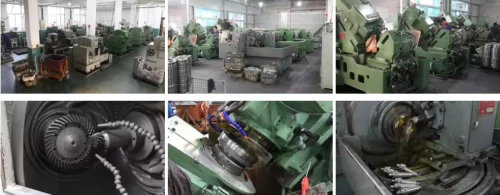
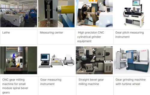
How Bevel Gears Are Manufactured: The Production Process
The bevel gear manufacturing sequence has eight defined stages — each one building on the previous, with no opportunity to correct errors from an earlier step without restarting from that point.
Australia Ever-Power's supply partners follow this controlled process, with every stage logged in a computerised tracking system for full traceability from raw material to dispatch.
Design
Gear ratio, tooth profile, module, pressure angle, and cone geometry defined using AutoCAD or SolidWorks. For spiral bevel gears, Gleason-proprietary software optimises the spiral angle and tooth crowning for the target contact pattern. FEA stress verification performed for all gears above M6.
Material Selection
Material chosen from steel alloys, cast iron, bronze, brass, aluminium, or non-ferrous alternatives based on load, speed, environment, and cost. For Australian food-processing applications, 316 stainless or food-grade acetal is specified. All raw materials verified against mill certificates before machining.
Gear Blank Preparation
Blanks turned from certified bar stock or forgings to bore, face, and OD dimensions at IT6 tolerance. CMM runout check performed — any blank exceeding 0.01 mm total runout is re-machined before tooth cutting to prevent compound geometric errors in the finished gear.
Gear Cutting
Three cutting methods used depending on tooth form and volume: Gleason method for spiral bevel gears (generating process with rotating cutter); Coniflex method for straight bevel gears (curved cutter simultaneously generating profile and depth); face milling for small-batch custom orders. All CNC-controlled for repeatability.
Heat Treatment
Case carburising and quenching achieves 58–62 HRC tooth surface hardness. Tempering after quenching relieves residual stress and improves toughness for shock-loaded applications. Nitriding used for precision gears where distortion must be minimised. Full time-temperature records retained per IATF 16949 traceability requirements.
Finishing Operations
Post-heat-treatment grinding achieves Ra ≤ 0.8 µm surface finish and corrects thermal distortion. Honing and lapping further reduce surface roughness to Ra ≤ 0.4 µm for precision grades. Contact pattern verified by blue-dye check — acceptable result is a centred oval covering 50–65% of face width.
Inspection & QC
100% CMM dimensional inspection for precision grades. Parameters measured: pitch error, tooth form, lead, runout — all compared against ISO 17485 tolerance bands for the specified accuracy grade. Hardness testing, surface finish measurement, and contact pattern confirmation complete the inspection sequence.
Surface Treatment & Dispatch
Optional surface treatments applied: coating, plating (nickel, zinc), black oxide, or passivation for corrosion resistance or specific environmental requirements. Full QA documentation package compiled and shipped with every order. Vacuum packing with plastic tray for transit protection.
How to Select the Right Bevel Gear: A Step-by-Step Guide
Bevel gear selection is a six-step process — each step narrows the specification until only one correct combination of type, material, module, and accuracy grade remains for the application.
This framework is used by Australia Ever-Power's engineering team when reviewing applications from customers across Sydney, Melbourne, Brisbane, Adelaide, Darwin, and Perth.
① Determine Application Requirements
Define the required torque (Nm), shaft speed (rpm), gear ratio, shaft intersection angle, operating temperature range, and environment (indoor clean / outdoor / food-contact / marine). These six inputs define every other specification parameter downstream. State them clearly on any enquiry — they cannot be assumed from a part number alone.
② Calculate Gear Parameters with Service Factor
Design torque = Nominal torque × KA (AGMA service factor). Apply KA = 1.0 for smooth uniform loads; 1.25–1.5 for moderate shock; 1.75–2.5 for heavy shock. Calculate module from the design torque and required face width using ISO 10300 or AGMA 2003 rating methods. Pitch diameter = Module × Number of teeth. Face width is typically 8–12× module for industrial bevel gears.
③ Select the Correct Tooth Form
Use straight bevel gears for pitch-line velocities below 5 m/s where cost is the primary driver. Use spiral bevel gears for velocities above 5 m/s, high-load applications, or where noise must stay below Safe Work Australia's 85 dB(A) action level. Use hypoid gears only when offset axes are a design requirement — and always specify EP hypoid lubricant, not standard gear oil. Use zerol bevel gears for medium-speed precision applications where the tooth form must be produced without spiral cutting capability.
④ Choose Material and Heat Treatment
Steel alloys (20CrMnTi, 42CrMo) case-hardened to 58–62 HRC for most industrial drives. 316 stainless with passivation for food-processing and marine environments — mandatory for FSANZ compliance. Bronze or brass for low-load, low-noise instrument drives. Cast iron for slow heavy drives where machinability and cost matter more than strength-to-weight ratio. POM/acetal for silent low-load drives in medical or consumer products.
⑤ Evaluate Efficiency and Power Loss
Bevel gear efficiency is primarily governed by tooth profile, surface finish, and lubrication quality. Spiral bevel gears at ISO Grade 5–6 with correct lubrication achieve 97–99% efficiency. Compare this with worm gear alternatives at the same ratio (60–90%) — the difference translates directly into energy savings that are increasingly significant under Australian electricity pricing and carbon accounting frameworks. For Australian manufacturers with EREP obligations, efficiency improvement documentation from drive upgrades is a reportable measure.
⑥ Specify Noise, Lubrication, and Documentation
For noise-sensitive applications, specify spiral bevel at DIN Grade 6 with lapped finish — this adds 8–15 dB(A) noise reduction versus straight bevel equivalents. For lubrication: ISO VG 150–220 gear oil (ISO 12925-1 Category CKD) for enclosed drives above 500 rpm; NLGI Grade 2 lithium grease for slow sealed drives; NSF H1-registered food-grade oil for food-contact applications. Request the full QA documentation package — chemical composition, CMM dimensional, hardness, heat treatment — for any safety-critical or compliance-audited application.
Key Advantages of Bevel Gears Over Alternative Drive Solutions
Bevel gears offer a combination of efficiency, compactness, load capacity, and design flexibility that alternative right-angle drive solutions — worm gears, universal joints, chain drives — cannot match simultaneously.
The comparison below quantifies the practical advantages relevant to Australian industrial buyers.
| Feature | Bevel Gear | Worm Gear | Universal Joint | Chain Drive |
|---|---|---|---|---|
| Mechanical Efficiency | 97–99% | 60–90% | 95–98% | 95–98% |
| Compact Envelope | Very compact | Compact | Moderate | Large |
| Speed Capability | Up to 8,000 rpm | Up to 3,000 rpm | Low–Medium | Medium |
| Load Capacity | High | Medium | Medium | High |
| Noise Level | Low (spiral) | Low–Moderate | Moderate | Moderate–High |
| Maintenance Frequency | Low | Low | Moderate | High |
| Precise Motion Control | Excellent | Good | Moderate | Moderate |
Applications of Bevel Gears in Australian Industry
Bevel gears appear in virtually every sector of Australian manufacturing and engineering — wherever rotational power must change direction, a bevel gear is almost certainly the most efficient and durable solution available.
The sector map below covers the primary Australian industries served by Australia Ever-Power from Condell Park NSW.
| Industry | Application | Bevel Gear Type | Key Requirement |
|---|---|---|---|
| Automotive | Differentials, PTO units (VIC, QLD) | Spiral bevel / Hypoid | High load, PPAP documentation |
| Power Tools | Angle grinders, drills, saws (all states) | Straight bevel / Spiral bevel | Compact, sealed-for-life |
| Printing Presses | Web offset drives, folder sections (NSW, VIC) | Zerol bevel | Low noise, precise phasing |
| Industrial Machinery | Conveyors, mixers, reducers (all states) | Spiral / Straight bevel | Efficiency, serviceability |
| Agricultural Machinery | PTO drives, harvesters (SA, WA, VIC) | Straight / Spiral bevel | Field-replaceable, cost-efficient |
| Marine | Propulsion gearboxes, steering (QLD, VIC) | Spiral / Hypoid | Corrosion resistance, reliability |
| Medical Devices | Surgical robots, imaging systems (NSW, VIC) | Zerol bevel / Straight bevel | Biocompatibility, low backlash |
| Mining | Conveyor drives, crushers (WA, QLD) | Spiral bevel (heavy) | Extreme load, shock, traceability |
Bevel Gear Maintenance, Easy Servicing & Replacement Guide
One of bevel gears' practical advantages over chain drives and belt systems is the low maintenance frequency required — in a properly specified and lubricated enclosed drive, the primary maintenance tasks are oil inspection, level check, and periodic contact pattern verification.
The following maintenance schedule reflects best practice for Australian industrial bevel gear drives, aligned with AGMA 9005-F16 (Industrial Gear Lubrication) recommendations.
Routine Maintenance Schedule
| Interval | Task | Tool / Method |
|---|---|---|
| 500 hours | Oil level check; visual inspection for leaks | Dipstick / sight glass |
| 1,000–2,000 hours | Oil sample analysis (viscosity, particle count, water content) | ISO 4406 / ASTM D445 |
| 3,000–5,000 hours | Full oil change; check backlash; inspect seals | Dial indicator; AGMA 9005-F16 |
| 10,000 hours | Contact pattern check; bearing inspection; gear wear measurement | Blue-dye; micrometer |
| At failure signs | Root cause analysis; replace as matched pair | CMM inspection / hardness check |
The most important maintenance rule for bevel gears — and the one most frequently ignored in Australian maintenance programmes — is the matched-pair replacement rule: when one gear in a bevel pair fails or shows significant wear, both the pinion and crown gear must be replaced together. Fitting a new pinion against a worn crown (or vice versa) creates a mismatched contact geometry that drives failure of the new component within 500–1,500 hours, negating the cost of the new part entirely.
Bevel Gear Price Guide for Australian Buyers
Bevel gear pricing spans a 200× range from miniature brass instrument gears to large-module industrial mining pairs — understanding the cost drivers allows procurement managers to set realistic budgets and challenge quotes that are out of range.
The indicative price table below is in Australian dollars (AUD) inclusive of GST, based on Q1 2026 market data.
| Category | Module | Material | Type | Price (AUD / pair) |
|---|---|---|---|---|
| Miniature / Instrument | M0.15–M0.8 | Brass / POM | Straight / Zerol | $18 – $95 |
| Standard Industrial | M1–M3 | Steel / SS316 | Straight / Spiral | $65 – $380 |
| Precision Industrial | M2–M6 | Alloy steel (HT) | Spiral bevel | $380 – $1,800 |
| Heavy Industrial | M6–M12 | 20CrMnMo / 42CrMo | Spiral bevel | $1,800 – $12,000 |
| Large Module / Mining | M12–M20 | 20CrNi2MoA | Spiral bevel | $12,000 – $85,000+ |
| Custom OEM / ODM | Any | Per specification | Any | POA — quote within 48 hrs |
Prices are indicative market ranges including GST. Final pricing depends on quantity, exact geometry, heat treatment specification, accuracy grade, surface treatment, documentation requirements, and delivery method. Contact Australia Ever-Power for a firm quotation within 24 hours.
Sustainability, Compliance & Global Trade
🌿 Material Sustainability
Steel bevel gear scrap is 100% recyclable through electric arc furnace processes — Australia's largest steel recycler, operating in Sydney, Melbourne, and Brisbane, accepts certified alloy steel swarf from gear manufacturing. Gear designs that extend service life by 2× from correct specification selection reduce the embedded carbon of replacements by the equivalent amount over the drivetrain's operational life.
⚡ Drive Efficiency & Energy Savings
Replacing worm gear right-angle drives with spiral bevel gear drives improves efficiency from a typical 74% to 98% — a 24-percentage-point gain. For a 30 kW motor running 6,000 hours per year at $0.28/kWh, that gap saves approximately $12,100 per drive per year. Across a facility with 15 right-angle drives, the annual saving exceeds $180,000 — a figure that is directly reportable under Australia's EREP energy efficiency framework.
📋 Australian Compliance
AS 4024.1 series governs guarding and risk assessment for machinery containing bevel gears. AS 2938 covers geometric data and terminology. AS 4674 and FSANZ standards apply for food-contact applications. For mining plant, state-specific legislation (QLD Mines Safety Act, WA Mines Inspection Act) applies in addition to federal WHS Regulations. Australia Ever-Power provides gear documentation in formats supporting all these compliance frameworks.
🌏 Global Trade Reach
Bevel gears are one of the most globally traded mechanical components (HS 8483.10). Primary manufacturing hubs are Germany, Japan, USA, Taiwan, and China; major consuming markets include Australia, New Zealand, Southeast Asia, and the Middle East. Australia Ever-Power supports export orders to New Zealand, PNG, and Pacific Island nations with full export documentation, CPTPP tariff preference certificates, and multi-destination freight coordination.
Why Choose Australia Ever-Power for Bevel Gears?
Australia Ever-Power operates as a technical partner for Australian manufacturers across every bevel gear category — from miniature M0.15 instrument gears to M20 mining giants — with a single engineering review process that confirms correct specification before any order is placed.
🏭 Local Sydney Stock
Standard bevel gear pairs in straight, spiral, and miter configurations stocked at 27 Harley Crescent, Condell Park NSW 2200. Same-week dispatch to Sydney metro and 2–3 business days nationally by DHL or UPS.
📐 ISO 9001 & IATF 16949
Full QA documentation — chemical composition, mechanical performance, CMM dimensional inspection, heat treatment records — supplied as standard with every order. PPAP documentation for automotive and mining OEM supply chains.
🔧 OEM / ODM Custom Manufacturing
Custom bevel gears from drawings (DXF/DWG/STEP/PDF) or physical samples. Quote within 48 hours. Sample: 3–5 days (stock) or 20 days (custom). Bulk: 25–30 days. All modules and materials available.
🔬 Free Engineering Review
Pre-purchase application review covering ratio, torque, service factor, module, material, accuracy grade, and lubrication. We flag specification mismatches before they become production failures. Customer IP protected under NDA throughout.
📦 Nationwide & Export Delivery
DHL and UPS dispatch to all Australian states and territories. International export capability with full customs documentation. Sea and air freight options for all order sizes.
📍 Our Address
Australia Ever-Power
27 Harley Crescent
Condell Park NSW 2200
Mon–Fri, AEST business hours
What Australian Customers Say
Paul Dimitriou
Production Engineer — Automotive Components, Altona VIC
"We needed a reliable source for M3 and M4 spiral bevel gear pairs in 20CrMnTi for our automotive differential testing rigs. Our previous supplier's lead times were unpredictable — sometimes 8 weeks, sometimes 12. Australia Ever-Power quoted same-week dispatch from Sydney stock for our standard sizes and had PPAP documentation ready within the first order. The gears have been running 14 months in continuous test duty without a single failure. Supply reliability and documentation quality are exactly what an IATF 16949 audit requires."
Fiona Blackwood
Maintenance Engineer — Power Tools Manufacturer, Penrith NSW
"We manufacture angle grinders for the Australian trade market and go through roughly 45,000 straight bevel gear pairs per year in M1.5 brass. Ever-Power set up a blanket order arrangement with quarterly releases — consistent pricing, priority dispatch, and matched-pair quality that has kept our field warranty return rate for gear-related failures below 0.3%. The engineering team also helped us identify a bore tolerance issue on an early batch before it reached production — that kind of proactive support is genuinely rare in component sourcing."
Henry Nakamura
Engineering Manager — Industrial Machinery OEM, Yatala QLD
"Our conveyor drive redesign required switching from worm gear right-angle drives to spiral bevel gears across 18 drive points. Before committing to the redesign, we used Ever-Power's free engineering review — they confirmed gear ratios, recommended M5 42CrMo spiral bevel pairs at DIN Grade 6, and flagged that our original housing design would have generated excessive axial thrust on the bearings. The redesign has been running 16 months: measured efficiency at 97.4% versus the old worm drives' 71%. Annual electricity saving across the 18 drives: approximately AUD $94,000."
Victoria Stanton
Quality Manager — Medical Device Manufacturer, North Ryde NSW
"We source M0.5 zerol bevel gears in 316 SS for a surgical instrument application — biocompatibility, full material traceability, and sub-3 arc-minute backlash are all non-negotiable requirements. Ever-Power understood the application immediately, supplied the correct passivated 316L grade, and included the material certificate and CMM report formats our TGA audit requires. We trialled samples from three suppliers; Ever-Power was the only one whose first-off samples passed our incoming inspection without a re-submission. We've been ordering production quantities for 18 months without a single non-conformance."
Frequently Asked Questions About Bevel Gears
Customer Success Cases
Case Study: Upgrading 18 Conveyor Drives from Worm Gears to Spiral Bevel in QLD
Industrial Machinery OEM — Yatala QLD | Component: M5 42CrMo spiral bevel pairs, DIN Grade 6
Challenge: 18 worm gear right-angle drives running at an average 71% efficiency on a packaging conveyor system. Rising electricity costs and an EREP reporting obligation prompted the customer to investigate efficiency improvements. Each 30 kW drive was losing approximately 8.7 kW as heat — generating thermal management costs and reducing motor life through sustained overtemperature operation.
Solution: Australia Ever-Power engineering review recommended M5 42CrMo spiral bevel pairs at DIN Grade 6, housed in modified gearbox bodies compatible with the existing shaft centres. Pre-purchase FEA confirmed tooth-root strength at the design torque with a 1.8× service factor.
Result: Post-retrofit measured efficiency: 97.3% average across 18 drives. Annual electricity saving: AUD $94,000 at current tariffs. Gearbox operating temperature dropped 22°C on average. EREP audit team accepted the efficiency improvement as a documented engineering measure, contributing to the customer's mandatory reduction target. Payback period: 14 months from retrofit cost.
Case Study: Rapid Custom Bevel Gear Supply for an Adelaide Defence Contractor
Defence Equipment Subcontractor — Adelaide SA | Component: M2 hypoid bevel gear pairs, 42CrMo4, DIN Grade 5
Challenge: A defence project required M2 hypoid bevel gear pairs in 42CrMo4 at DIN Grade 5 with full AS 9100D material traceability and first-article inspection report. The original overseas supplier had a 16-week lead time — incompatible with the project schedule. Two alternative suppliers could not provide the AS 9100D documentation format required by the prime contractor.
Solution: Australia Ever-Power sourced the gears through an AS 9100D-certified manufacturing partner, completed engineering review and drawing approval within 48 hours, and supplied samples in 17 business days with full first-article documentation including material certs, CMM dimensional report, hardness survey, and heat treatment records — all in formats accepted by the prime contractor's QA team.
Result: Samples accepted on first submission with no RFIs. Production quantities delivered to project schedule. The prime contractor approved Australia Ever-Power as a qualified bevel gear supplier for the project series, with three subsequent production orders placed within 12 months. Customer IP protection was maintained under NDA throughout, with no drawing sharing outside the direct supply chain.
Find the Right Bevel Gear for Your Application — First Time
Talk to Australia Ever-Power's engineering team at 27 Harley Crescent, Condell Park NSW 2200.
We review your application, confirm tooth form, module, material, and accuracy grade, and return a firm quote within 24 hours.
Stock items ship same week. Custom gears manufactured in 20–30 days.
Serving all Australian states, territories, and export markets.
📍 27 Harley Crescent, Condell Park NSW 2200 | ISO 9001:2015 Certified | All Types & Modules | DHL & UPS Dispatch