Designing bevel gear reducers requires balancing intersecting shaft geometry, load distribution, thermal management, and long-term reliability. Engineers worldwide have tackled these challenges in mining conveyors, agricultural machinery, marine propulsion, and renewable energy systems. This guide draws on decades of practical experience to share proven design approaches, common pitfalls, and actionable recommendations for creating durable, efficient bevel gear reducers. Whether developing a new multi-stage unit or upgrading an existing drive, the principles outlined here help achieve optimal performance while minimising downtime in demanding Australian industrial environments.
Multi-stage bevel gear reducer assembly for heavy industrial use
Core Principles of Bevel Gear Reducer Design
Successful bevel gear reducer design begins with accurate definition of the shaft angle—most commonly 90°—and the required gear ratio. The pitch cone angles must sum exactly to the shaft angle, calculated using established formulae from ISO 23509. Engineers must then determine module, face width (typically limited to one-third of the cone distance), and tooth counts that avoid undercutting while providing adequate bending strength.
Axial and radial thrust forces inherent to bevel geometry demand careful bearing selection and housing stiffness analysis. Multi-stage reducers often combine bevel and helical or planetary stages to achieve high overall ratios with compact footprints. Thermal expansion, lubrication flow, and sealing against contaminants further influence housing design and material selection.
Australia Ever-Power engineering teams routinely apply these principles when developing custom reducers for local mining and agricultural clients, ensuring every unit matches the precise operating conditions of the installation site.
Standards and Calculation Methods Used by Experienced Designers
Professional designers rely on ANSI/AGMA ISO 23509 for bevel and hypoid gear geometry, ISO 10300 for load capacity, and AGMA 2005 for comprehensive design guidance. These standards provide methods for rating bending and contact strength while accounting for load spectrum, lubrication, and safety factors. Advanced teams incorporate loaded tooth contact analysis (LTCA) software to optimise ease-off topography and extend service life under variable loading.
For critical applications, finite element analysis verifies housing deflection and bearing life under maximum torque. Service life predictions integrate cumulative damage hypotheses, considering displacement of the pinion relative to the gear under different load cases. Experienced engineers always validate calculations with prototype testing before series production.
At Australia Ever-Power, all designs undergo rigorous verification against these international standards, supplemented by local experience with Australian operating conditions such as high dust loads and wide ambient temperature ranges.
Precision spiral bevel gears during quality inspection
Step-by-Step Design Process for Bevel Gear Reducers
Collect input power, speed, duty cycle, shaft angle, operating environment, and target service life. Specify shock factors for mining or agricultural applications.
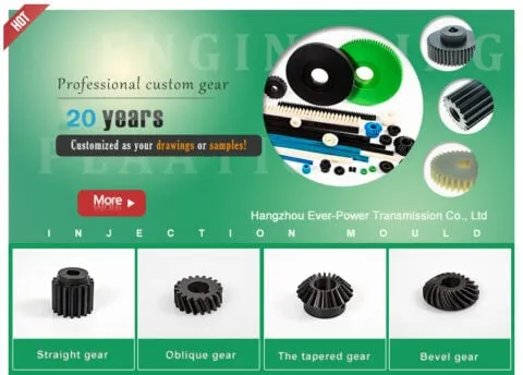
Choose straight, spiral, zerol, or hypoid bevel gears based on speed and noise requirements. Distribute ratios across stages for optimal pinion strength.
Determine pitch cone angles, module, face width, and cone distance using ISO 23509. Verify both cone angles are positive and sum correctly to the shaft angle.
Apply ISO 10300 or AGMA methods for bending and pitting safety factors. Incorporate LTCA for optimised tooth contact under load.
Ensure adequate stiffness to limit deflection. Select bearings rated for combined radial and axial loads with appropriate life calculation.
Choose oil or grease system with proper viscosity and filtration. Design effective seals and breathers for dusty or wet conditions.
Manufacture prototypes, conduct contact pattern checks, noise and vibration testing, and endurance runs before final production.
Common Design Challenges and Lessons from Real Projects
One frequent issue arises when designers assume catalogue 90° gears will perform correctly in slightly different housing angles. Even 0.5° deviation can destroy tooth contact. Experienced teams always measure actual housing geometry or specify custom pitch cone angles.
Another challenge involves thermal management in enclosed reducers operating in hot Australian climates. Inadequate ventilation or lubricant selection leads to overheating, viscosity breakdown, and accelerated wear. Successful designs incorporate cooling fins, oil pumps, or synthetic lubricants with high thermal stability.
Misalignment during installation remains a leading cause of premature failure. Precision dowel pins, laser alignment tools, and torque-sequenced bolting procedures mitigate this risk effectively.
Case Study: Mining Conveyor Reducer Upgrade
A major Hunter Valley coal operation experienced repeated spiral bevel gear failures in conveyor drives. Analysis revealed insufficient face width and marginal safety factors under shock loading. Redesign with increased module, optimised spiral angle, and upgraded carburized steel extended service life from 8,000 to over 35,000 hours. Australia Ever-Power supplied the custom sets with full documentation and on-site support.
Bevel gear reducer installed in mining conveyor application
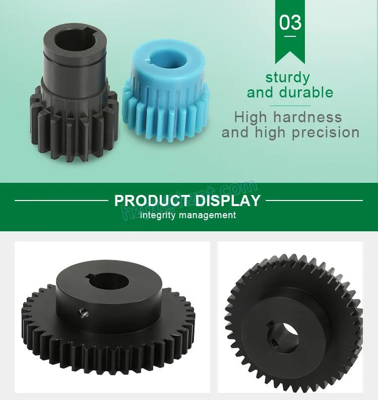
Material Selection and Manufacturing Considerations
High-quality case-hardening steels such as 18CrNiMo7-6 or 8620 deliver excellent tooth strength after carburizing and grinding. For corrosive environments, stainless or specially coated variants provide long-term protection. Face width, crowning, and root fillet optimisation during manufacturing directly influence fatigue resistance.
Modern CNC bevel gear generators and lapping processes achieve the precise tooth geometry required for quiet, efficient operation. Australia Ever-Power maintains full control over heat treatment and finishing to ensure every reducer meets or exceeds international quality grades.
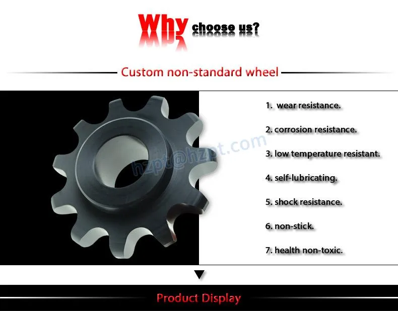
Practical Recommendations for Australian Conditions
- Dust and Moisture Protection: Use labyrinth seals combined with positive pressure breather systems in mining and agricultural settings.
- Shock Load Handling: Apply service factors of 1.5–2.5 and incorporate flexible couplings to protect gear teeth.
- Maintenance Access: Design inspection ports and drain points for easy field servicing without full disassembly.
- Thermal Management: Specify synthetic lubricants and consider oil coolers for continuous duty in high ambient temperatures.
These measures, refined through years of local project experience, significantly reduce unplanned downtime.
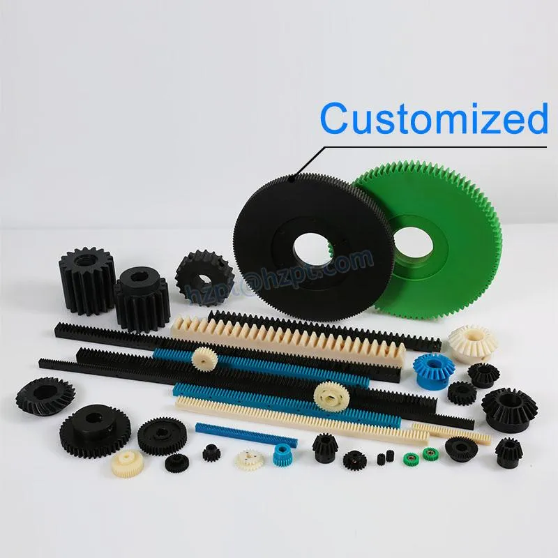
Related Product: Custom Bevel Gear Reducers
Australia Ever-Power offers fully customised spiral bevel gear reducers engineered for your exact duty cycle, shaft configuration, and environmental challenges. From single-stage right-angle units to multi-stage combinations, every reducer receives complete design documentation and performance guarantees.
Custom-designed bevel gear reducer ready for shipment
Customer Experience and Success Stories
“The custom bevel reducer designed by Australia Ever-Power for our grain harvester solved persistent overheating issues. After 18 months of continuous operation in dusty conditions, performance remains excellent.”
“Their engineering team redesigned our conveyor drive bevel set with improved tooth geometry. Failures dropped to zero and we gained measurable efficiency improvements.”
Australia Ever-Power vs Other Suppliers in Reducer Design Capability
Frequently Asked Questions
Ready to Design or Upgrade Your Bevel Gear Reducer?
Australia Ever-Power | 27 Harley Crescent, Condell Park NSW 2200 | [email protected]