The module (m) is the fundamental sizing parameter in metric bevel gear design, defining tooth size and directly influencing strength, torque capacity, and physical dimensions. Unlike imperial diametral pitch used in some regions, the module system — standardised under ISO 23509 and DIN 3971 — provides a rational, metric-based framework that simplifies calculation and manufacturing of straight bevel gears, spiral bevel gears, zerol bevel gears, and hypoid gears. Selecting the correct module is critical: too small and the gear set will fail prematurely under load; too large and the assembly becomes unnecessarily heavy, expensive, and inefficient. This technical guide explains the bevel gear module system in detail and provides clear, practical steps for choosing the optimum specification for your application.
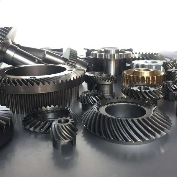
Bevel gear module comparison showing different tooth sizes
Understanding the Module (m) in Bevel Gear Design
The module is defined as the pitch circle diameter divided by the number of teeth (m = d / z), expressed in millimetres. It represents the size of the tooth in the transverse plane at the large (outer) end of the bevel gear. All linear dimensions of the gear — including pitch diameter, addendum, dedendum, and whole depth — are directly proportional to the module.
For bevel gears, the module is always specified at the large end of the tooth (outer module). Because the tooth size decreases toward the cone apex, the actual tooth proportions vary along the face width. This tapering effect makes correct module selection even more important than in parallel-shaft spur gears.
ISO and AGMA standards recommend a standard series of modules for bevel gears: 1.0, 1.25, 1.5, 2.0, 2.5, 3.0, 4.0, 5.0, 6.0, 8.0, 10, 12, 16, 20. Australia Ever-Power stocks and manufactures bevel gears across this full range, ensuring rapid availability for both standard and custom shaft angle designs.
Why Module Selection Directly Affects Performance
The chosen module governs bending strength, surface durability (pitting resistance), and overall gear size. Larger modules produce stronger, stiffer teeth capable of transmitting higher torque but increase weight, inertia, and cost. Smaller modules allow more compact designs and higher ratios within a given envelope, but tooth root stress rises rapidly and manufacturing tolerances become more critical.
In bevel gears, module also influences the cone distance and face width limitations. Recommended maximum face width is normally one-third of the cone distance (b ≤ R/3) to maintain reasonable tooth proportion variation. Selecting an inappropriate module can force either an excessively wide face (risking tooth tip breakage) or an undersized gear set that fails under load.
Australia Ever-Power engineers always balance module selection with pitch cone angle, material, and duty cycle to achieve the most economical and reliable solution.
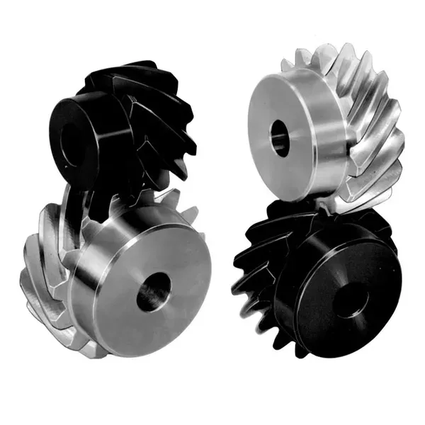
Module series comparison chart for bevel gears
Step-by-Step Guide to Selecting the Correct Bevel Gear Module
Calculate input power (kW) and pinion speed (rpm). Apply appropriate service factors for shock loading (1.5–2.5 for mining/agricultural duty).
Define ratio i = z₂/z₁ and shaft angle Σ (most commonly 90°). Calculate pitch cone angles using ISO 23509 formulae.
Use approximate formula: m ≈ (2 × T × K) / (d₁ × σ_F × Y), where T is torque, K is a material/load factor, σ_F is allowable bending stress, and Y is the Lewis form factor. Refine with ISO 10300 rating.
Ensure b ≤ R/3 and b ≤ 10m. If limits are exceeded, increase module or adjust ratio/stages.
Choose the smallest standard module that satisfies strength and geometric constraints. Verify both bending and contact safety factors ≥ 1.2–1.5 depending on application criticality.
Perform complete ISO 10300 or AGMA rating for pitting and bending. Adjust module upward if safety margins are insufficient.
Standard Module Series and Typical Applications
Practical Selection Checklist for Australian Conditions
- Apply service factor 1.75–2.5 for shock-loaded mining and quarrying applications.
- For high ambient temperatures, derate allowable stress or select a larger module.
- Consider face width limitation b ≤ R/3; if exceeded, increase module or use multiple stages.
- Verify both bending and contact safety factors using full ISO 10300 calculation.
- Account for non-90° shaft angles — these often require slight module adjustment due to altered cone geometry.
Related Product: Full Range of Bevel Gears by Module
Australia Ever-Power maintains extensive stock and custom manufacturing capability across the complete metric module range for straight bevel gears, spiral bevel gears, and hypoid sets. Whether you need a precision module 2.0 set for robotics or a heavy-duty module 12 set for mining conveyors, our team can supply matched pairs calculated for your exact shaft angle and duty cycle.
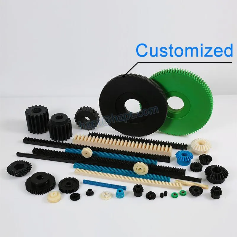
Custom bevel gear set manufactured to exact module specification
Customer Success Stories
“Australia Ever-Power helped us select the optimal module 5 spiral bevel set for our new conveyor drive. The gears have run flawlessly for over 18 months under continuous heavy load.”
“Their technical team quickly recommended module 3.0 instead of our initial 2.5 choice, preventing early failure and saving us significant downtime.”
Frequently Asked Questions
Need Help Choosing the Right Bevel Gear Module?
Australia Ever-Power | 27 Harley Crescent, Condell Park NSW 2200 | [email protected]