The Selection Question Engineers Face on Every Right-Angle Drive
Once a designer commits to bevel gears for an application, a second decision immediately follows: straight bevel or spiral bevel? On the surface this appears simple — spiral bevel gears are widely considered the superior configuration, so why not always use them? In practice that framing ignores the real engineering trade-offs. Straight bevel gears are not inferior gears; they are a different configuration with genuine advantages in specific operating conditions. Choosing spiral bevel gears where straight bevel gears are adequate wastes money and adds unnecessary lead time. Choosing straight bevel gears when the application genuinely demands spiral bevel performance results in accelerated wear, noise complaints, and premature failure well inside the design life.
The selection decision rests on four primary engineering parameters: pitch-line velocity, transmitted load and contact ratio requirements, acceptable noise level, and total cost of ownership across the gear set’s expected service life. Each parameter has a threshold region where the balance tips decisively from one type to the other. This guide walks through each threshold with the quantitative guidance needed to correctly place your application on the decision framework.
Australia Ever-Power, Condell Park NSW 2200, manufactures both gear types and assists Australian engineers with configuration selection across mining, agriculture, marine, food processing, and industrial sectors. Contact [email protected] for application-specific guidance at no charge.
The Speed Threshold: The Most Decisive Selection Criterion
Pitch-line velocity is the single most reliable selector between straight and spiral bevel gears. The pitch-line velocity v at the mean pitch circle of the ring gear is calculated as:
dm2 = mean pitch diameter of ring gear (mm) | n₂ = ring gear speed (RPM)
Published Speed Recommendations
Below 5 m/s pitch-line velocity, straight bevel gears are routinely used without performance penalty in general industrial applications. The dynamic load factor remains low, the acoustic difference between gear types is modest, and the simpler manufacturing route of straight bevel gears provides genuine cost value. Between 5 m/s and 8 m/s, the operating conditions enter a transitional zone — straight bevel gears still function but produce noticeably higher noise levels and begin to show dynamic load factors that reduce effective load capacity. Above 8 m/s, spiral bevel gears are strongly recommended by both AGMA and ISO standards because straight bevel gear dynamic behaviour becomes problematic: impact at tooth engagement creates shock loading that scales with the square of velocity, the resulting noise levels are difficult to manage in enclosed machinery, and fatigue life reduces rapidly.
The mechanism is straightforward. Straight bevel gear teeth engage across the full face width simultaneously — the load goes from zero to maximum in a single step as each tooth pair enters mesh. At low speeds this step-loading is manageable; at high speeds it creates a measurable impact force and acoustic impulse at each mesh event. Spiral bevel gear teeth enter engagement progressively from one end of the tooth to the other, distributing the load continuously rather than applying it as a sudden full-width impact. The progressive engagement eliminates the acoustic impulse and dramatically reduces the dynamic load component at high speeds.
Contact Ratio and Load Capacity: When Torque Makes the Choice
Even below the speed threshold, a load-intensive application can tip the selection toward spiral bevel gears. The reason is contact ratio. A straight bevel gear pair has a total contact ratio determined entirely by the transverse profile — typically 1.4 to 1.8. This means that during each mesh cycle, periods of single-tooth contact exist where the entire transmitted load is carried by one tooth pair. Peak contact stress and bending stress occur during this single-tooth contact period, which is precisely when surface fatigue initiates and tooth fracture risk is highest.
A spiral bevel gear at 35° spiral angle adds a face contact ratio component of typically 1.4 to 1.8, raising the total contact ratio to 2.2–2.8. With a total contact ratio above 2.0, two tooth pairs carry the load simultaneously throughout most of the mesh cycle. The load per tooth pair drops to 50–60% of the equivalent straight bevel value, reducing contact stress by 18–25% and roughly doubling the contact fatigue life for the same gear size and material. For a heavily loaded application at moderate speed, this load capacity advantage alone justifies the additional cost of spiral bevel gears, even if noise level is not a concern.
Worked Example: Load-Driven Selection
Application: Mining conveyor drive bevel stage, 45 kW, 480 RPM ring gear, mean ring gear diameter 200 mm
Pitch-line velocity: v = π × 200 × 480 / 60,000 = 5.03 m/s — borderline zone
Torque at ring gear: T = 45,000 / (2π × 8.0) = 895 Nm
Decision: High torque + shock loading from conveyor start-stop cycles → spiral bevel selected. The contact ratio advantage reduces peak tooth stress below the straight bevel equivalent rating, providing adequate life margin with the applied service factor KA = 1.75.
Noise Requirements: The Application Environment Decides
Noise requirements are the third major selector and frequently override speed considerations. An application operating at 3 m/s pitch-line velocity — well below the typical straight bevel speed limit — may still require spiral bevel gears if the gearbox is mounted inside an enclosed building, near personnel workstations, or in a noise-sensitive process environment. Indoor applications in food processing facilities, packaging plants, beverage bottling lines, and laboratory environments often have sustained noise exposure limits that straight bevel gears at medium speeds simply cannot meet, while spiral bevel gears can deliver acceptable acoustic performance across the same speed range.
The acoustic advantage of spiral bevel gears has two components. First, the progressive engagement eliminates the impulsive mesh excitation that straight bevel gears generate at each tooth contact. Second, the higher contact ratio reduces transmission error — the variation in angular velocity as each tooth pair engages and disengages — which is the primary noise excitation mechanism in any gear set. A straight bevel gear set at 5 m/s may generate 72–78 dB(A) at 1 metre; a spiral bevel set at the same speed and load can achieve 62–68 dB(A) — a 10 dB reduction representing roughly half the perceived noise level to human observers.
For Australian workplaces subject to Safe Work Australia noise exposure standards (85 dB(A) averaged over 8 hours, 140 dB(C) peak), the acoustic performance of the gear type can determine compliance without requiring costly acoustic enclosures or hearing protection programs. Choosing spiral bevel gears in a noise-sensitive indoor installation is often the lowest-cost noise control measure available at the design stage.
When Straight Bevel Gears Remain the Correct Choice
Straight bevel gears should not be reflexively upgraded to spiral bevel in every situation. There are real applications where the simpler gear type is genuinely the better engineering choice, and understanding these cases is as important as knowing when to use spiral bevel gears. The three strongest arguments for straight bevel gears are: low operating speed (below 3–5 m/s), interchangeability requirements without matched pairs, and hard cost constraints on low-criticality applications where failure consequences are minor.
Mitre gear applications — 1:1 ratio right-angle direction changes — are a classic case for straight bevel gears. Because both mating gears are identical, any mitre gear of the correct module meshes with any other without requiring matched pairs. This interchangeability makes stock management and field replacement simple and reliable. Converting a mitre application to spiral bevel introduces a hand-of-spiral directionality requirement and matched pair dependency that adds complexity without performance benefit at the typically low speeds of mitre gear applications in instrumentation, laboratory equipment, and light-duty machine tools.
Agricultural PTO gearboxes operating at 540 RPM or 1,000 RPM PTO shaft speed represent another case where straight bevel gears are commonly and correctly specified. The pitch-line velocities involved are below 3 m/s in most farm implement drives, the seasonal usage cycle means cumulative fatigue loading is modest, and the cost-sensitivity of agricultural equipment procurement is high. For these applications, straight bevel gears provide entirely adequate performance at a manufacturing cost that is 30–50% lower than equivalent spiral bevel gear sets.
Selection Decision Matrix
Use this matrix to quickly identify the recommended gear type for your application. Where multiple rows apply, the most demanding criterion governs.
| Application Criterion | Straight Bevel ✓ | Transitional Zone | Spiral Bevel ✓ |
|---|---|---|---|
| Pitch-line velocity | Below 5 m/s | 5 – 8 m/s | Above 8 m/s |
| Noise level (dB(A) at 1 m) | 75+ acceptable | 68–75 | Below 68 required |
| Shock / dynamic load | Smooth (KA ≤ 1.25) | Moderate | Heavy shock (KA ≥ 1.75) |
| Required contact ratio | 1.4–1.8 adequate | 1.8–2.2 | Above 2.2 needed |
| Interchangeability | Required (no matched pairs) | Preferred | Matched pairs acceptable |
| First cost priority | Primary driver | Balanced | Life cost more important |
Manufacturing Process Differences and Their Cost Implications
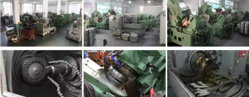
Straight bevel gears can be manufactured by form-milling using relatively standard milling machine equipment with a bevel gear cutter — a process that does not require the specialised Gleason or Klingelnberg face-milling machines needed for spiral bevel production. This means straight bevel gears can be produced by a wider range of general engineering workshops, lead times are typically shorter, and the machine setup cost per pair is lower. The tooling cost for a straight bevel form cutter is a fraction of the face-mill cutter head cost for spiral bevel production.
Spiral bevel gears require the specialised face-milling process (Gleason) or face-hobbing process (Klingelnberg Palloid) to generate the curved tooth form with the correct spiral angle, tooth taper, and crowning geometry. After cutting, spiral bevel gears typically undergo case carburising and hardening followed by either gear lapping in matched pairs (for AGMA Class 9–10) or CNC gear grinding to independently correct post-hardening distortion (for AGMA Class 11+). This full manufacturing sequence is longer and more capital-intensive than straight bevel manufacture, directly reflected in higher gear cost and longer lead times.
However, the total cost of ownership calculation frequently reverses this first-cost comparison. A straight bevel gear set costing AUD $300 that requires replacement every 3 years due to surface fatigue at the application’s operating load accumulates AUD $1,000 in gear cost plus associated maintenance labour over a 10-year machine life. A spiral bevel gear set costing AUD $900 that achieves the full 10-year design life at the same load represents the lower total cost — despite costing three times more at purchase. This lifecycle cost comparison is the correct economic framework for bevel gear type selection, particularly for continuously operating industrial machinery.
Industry Applications: Which Type Dominates and Why
Automotive Differentials — Spiral/Hypoid Universally
Pitch-line velocities of 10–40 m/s, noise sensitivity of vehicle passengers, and heavy cyclical loading all mandate spiral or hypoid bevel gears. No straight bevel differential has appeared in a production passenger vehicle since the early 20th century.
Mining Equipment — Spiral for Critical Drives, Straight for Auxiliary
Longwall shearer cutting drum drives, haul truck differentials, and drill rig rotary tables all use spiral bevel gears for their combination of high speed and heavy shock loading. Low-speed, low-load auxiliary drives like ventilation damper actuators may use straight bevel gears.
Agriculture — Straight Bevel Dominates Low-Speed PTO Drives
PTO-driven implements at 540–1,000 RPM operate at pitch-line velocities well below the speed threshold. Straight bevel gears meet performance requirements at lower cost. Combine harvester header drives at higher speeds and loads transition to spiral bevel configuration.
Machine Tools — Straight Bevel for Mitre, Spiral for Spindle Drives
Milling machine head mitre drives use interchangeable straight bevel gears. High-speed spindle drives and precision positioning mechanisms use spiral or zerol bevel gears for low transmission error and high contact ratio at elevated RPM.
Price Comparison: Straight vs Spiral Bevel Gears (AUD)
Indicative single-pair pricing, Module 4, case-hardened alloy steel. Contact [email protected] for project quotations.
| Configuration | AGMA Class | Price / Pair | Lead Time | Best Suited For |
|---|---|---|---|---|
| Straight bevel (form milled) | 7–8 | $180–$380 | 2–3 weeks | Agriculture, mitre, low-speed auxiliary |
| Spiral bevel (lapped, AGMA 9–10) | 9–10 | $700–$1,400 | 3–5 weeks | Industrial gearboxes, automotive, marine |
| Spiral bevel (CNC ground, AGMA 11) | 11 | $1,600–$3,200 | 5–7 weeks | Mining, precision drives, high-speed |
| Stainless spiral bevel (food-grade) | 8–10 | $900–$2,000 | 4–6 weeks | Food processing, marine deck |
Related Components and Accessories
Tapered Roller Bearings
Essential for both types. Spiral bevel gears generate higher axial thrust from the spiral angle — bearing preload settings differ between straight and spiral bevel applications and must be adjusted accordingly.
Shim Packs (Mounting Distance)
Precision shim sets control mounting distance and bearing preload. Spiral bevel gears require tighter mounting distance tolerance (±0.05 mm vs ±0.15 mm for straight bevel) — use finer shim increments.
Gear Oil (GL-4 / GL-5)
Straight bevel gears operate satisfactorily with GL-4. Spiral bevel gears benefit from GL-4 or GL-5. Note: if the application is actually hypoid geometry, GL-5 hypoid oil is mandatory — never GL-4.
Engineer’s Blue (Marking Compound)
Required for contact pattern verification on both gear types. Spiral bevel contact pattern verification is more critical given the tighter mounting distance tolerance — never skip this step after assembly.
Gearbox Housing / Casing
Housing rigidity is more critical for spiral bevel gears. Under tooth load, housing deflection shifts the contact pattern; straight bevel gears tolerate more housing flex before edge contact develops.
Lip Seals and Breather Vents
Identical sealing requirements for both types. Replace seals at every major overhaul — contamination is the leading premature wear cause for both straight and spiral bevel gears in Australian industrial environments.
Australia Ever-Power vs Other Suppliers: Selection Support
The bevel gear type selection decision is engineering work — it requires understanding the application’s speed, load, noise, and cost parameters and applying the correct technical framework. Catalogue distributors and import agents supply what they stock; they rarely provide the engineering guidance needed to make the correct selection. Australia Ever-Power provides genuine engineering consultation as part of every enquiry.
| Capability | Ever-Power | Distributors | Import Agents |
|---|---|---|---|
| Type selection engineering support | ✓ Yes | ⚠ Limited | ✗ No |
| Both straight and spiral in-house | ✓ Yes | ⚠ Some | ✗ Catalogue |
| Lifecycle cost analysis provided | ✓ Yes | ✗ No | ✗ No |
| Custom non-standard configuration | ✓ Yes | ✗ No | ⚠ Slow |
Customer Experiences with Gear Type Selection
“We were about to specify spiral bevel gears for a low-speed PTO drive at 300 RPM — simply because they appeared more ‘professional’. Ever-Power pointed out that pitch-line velocity was 1.8 m/s and straight bevel gears at half the price would deliver identical service life. Saved us $600 per gearbox across a fleet of 14 machines.”
“Our packaging line gearbox used straight bevel gears at 12 m/s — the previous supplier had never questioned the spec. Noise levels were causing operator complaints. Ever-Power identified the speed was well above the straight bevel threshold and provided spiral bevel replacements. Noise dropped from 78 to 65 dB(A).”
“The lifecycle cost argument was the key insight. Our previous straight bevel sets in the mining conveyor drive were failing at 14 months under heavy loading. Ever-Power’s spiral bevel replacement at 2.5× the price has now run 28 months with no signs of fatigue. The total cost is less.”
“Our food processing mixer needed stainless bevel gears. Ever-Power assessed that our speed and load were in the borderline zone and recommended spiral bevel stainless to ensure adequate contact ratio for the washdown duty cycle. The extra margin has been worth it — no gear issues after 3 seasons.”
Frequently Asked Questions
Let Our Engineers Select the Right Bevel Gear Type for You
Australia Ever-Power · Condell Park NSW 2200 · Engineering-led gear type selection, custom manufacture, and full documentation for Australian industry.