Power transmission efficiency in bevel gear drives directly affects operating costs, heat generation, and the size of ancillary equipment required. A spiral bevel gear set operating at 94% efficiency rather than 98% wastes 4% of transmitted power as heat — for a 100 kW drive running 6,000 hours per year, that is 24,000 kWh per year of avoidable energy loss, equivalent to approximately AUD $4,800/year at current industrial electricity rates in New South Wales. For Australian operations under increasing energy cost pressure and sustainability reporting requirements, optimising bevel gear efficiency is both an engineering and a financial priority. This guide analyses every significant efficiency variable and quantifies the improvement each measure delivers.
How Bevel Gear Efficiency Is Defined and Measured
Bevel gear mechanical efficiency (η) is defined as output power divided by input power: η = P_out / P_in. The difference (1 − η) represents power lost as heat within the gear mesh and bearings. For a single stage of spiral bevel gears, efficiency typically ranges from 96–98% under well-lubricated, correctly installed conditions — compared to 97–99% for spur and helical gear pairs at equivalent speeds, and 80–95% for worm gear drives. The slightly lower efficiency of bevel versus parallel-axis gears reflects the inherent sliding component in bevel tooth contact, particularly in spiral and hypoid configurations.
Gear efficiency losses are categorised as: load-dependent losses (friction at the tooth mesh, proportional to transmitted torque and the coefficient of sliding friction) and load-independent losses (churning of oil by rotating gear members, windage of gear teeth through air or oil mist, and seal drag). At low loads, load-independent losses dominate and efficiency is low. At rated load, load-dependent losses dominate and efficiency approaches its maximum. Understanding which loss category is dominant in your application determines which improvement measure to prioritise.
For hypoid bevel gears — the type used in vehicle rear axle differentials — efficiency is lower than equivalent spiral bevel gears due to the significant sliding velocity across the offset tooth surfaces. Hypoid gear efficiency typically ranges from 93–97% per stage, versus 96–98% for spiral bevel. This is the fundamental reason that hypoid-equipped rear axle drives consume more fuel than portal axle alternatives, and why hybridised drivetrains seeking maximum efficiency often use ring-and-pinion bevel sets with minimal hypoid offset.
Tooth Profile and Geometry: The Fundamental Efficiency Driver
Pressure Angle Effects
The normal pressure angle (αₙ) directly affects the sliding velocity at the tooth contact zone and the ratio of sliding to rolling in the tooth mesh. Higher pressure angles (22.5°, 25°) produce taller, narrower teeth with higher flank curvature — which increases the EHD film thickness and slightly reduces the coefficient of sliding friction at the tooth contact. For high-efficiency precision bevel gears, some manufacturers specify 25° pressure angle rather than the standard 20°, gaining approximately 0.2–0.5% efficiency improvement at the cost of increased tooth sensitivity to mounting distance deviation.
Spiral Angle Optimisation
The spiral angle of spiral bevel gears (typically 35° for Gleason systems) controls the balance between axial thrust force and tooth overlap contact ratio. Higher spiral angles increase contact ratio (improving load distribution and reducing dynamic load factor) but also increase axial thrust on the supporting bearings — bearing losses increase with axial thrust. The optimum spiral angle for efficiency balances these two effects, and is typically 25–35° for most industrial spiral bevel gear applications. Deviating significantly below 25° reduces contact ratio and increases dynamic load; above 40° increases bearing axial thrust disproportionately.
Straight vs Spiral vs Hypoid: Efficiency Comparison
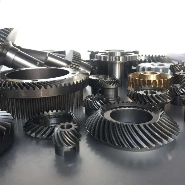
The tooth profile type has the largest single effect on bevel gear efficiency among geometric parameters. Straight bevel gears have pure rolling contact at the pitch point and modest sliding away from it — but their low contact ratio (≈1.0) means instantaneous load transfer produces high dynamic loads at higher speeds, increasing noise-related vibration energy losses. Spiral bevel gears achieve higher contact ratio with progressive load engagement, reducing dynamic loads and producing 0.5–1.5% higher efficiency at equivalent speeds compared to straight bevel gears. Hypoid gears have the highest sliding component and are 1–3% less efficient than spiral bevel of equivalent size and operating conditions — the trade-off accepted for the engineering advantages of offset shafts.
Lubrication: The Largest Controllable Efficiency Variable
Lubrication accounts for the largest share of controllable efficiency loss in most bevel gear applications. The two lubrication-related loss mechanisms are meshing friction losses (load-dependent, reduced by lower friction coefficient at the tooth contact) and churning losses (load-independent, reduced by lower oil viscosity and optimised oil level).
Oil Level and Churning Loss
Churning loss is often underestimated in bevel gear drives. A gearbox with oil level 30% above the specified height can lose 3–8% of input power in churning — the rotating gear members drag oil through the sump at high velocity, converting kinetic energy to heat. For splash-lubricated bevel gearboxes, maintaining oil level at the specified mark (±5 mm) rather than “keeping it full” is a direct efficiency measure. For high-speed bevel gear drives (above 15 m/s pitch line velocity), injected oil lubrication (oil jet directed at the tooth mesh rather than splash) eliminates churning loss entirely and is standard in racing and aerospace applications.
Installation Factors That Directly Affect Efficiency
Incorrect Mounting Distance and Contact Pattern
An off-centre tooth contact pattern (toe, heel, high, or low contact) concentrates load on a fraction of the tooth flank, increasing local contact pressure and friction. Edge loading from severe contact pattern errors can reduce overall gear mesh efficiency by 0.5–2.0% by increasing effective friction coefficient at the loaded edge contact zone. Setting the contact pattern correctly (centred, 65–70% tooth length) is the single most important installation step for achieving rated efficiency.
Bearing Preload and Friction
Bevel gear shaft bearings (taper rollers, angular contact) are preloaded to maintain mounting distance under axial thrust. Excessive preload increases bearing friction proportionally — a 50% over-preload can add 1–2% to total drivetrain losses. Under-preload shifts the gear members under load, deteriorating the contact pattern and reducing efficiency through edge loading. Both conditions must be avoided: set preload to the manufacturer’s specification, verified by rolling torque measurement.
Shaft Alignment and Housing Stiffness
Housing deflection under full load shifts the gear mounting distances from their set-up values, altering the tooth contact pattern. For drives where housing deflection under rated load exceeds 0.05 mm, the contact pattern must be set with calculated misalignment compensation (called “ease-off” in bevel gear terminology) so that under full load the pattern centres correctly. Without this compensation, the drive runs with edge loading at full load — its least efficient, most noise-generating condition.
Backlash Setting
Backlash below the minimum specification causes tooth binding during thermal expansion — forcing the teeth to push against each other on both flanks simultaneously. The resulting friction increases drive torque requirement and reduces efficiency. For drives subject to thermal cycling (outdoor Australian equipment, WA summer conditions), verify backlash at operating temperature — not only cold at assembly. Inadequate thermal expansion allowance in backlash setting is a significant efficiency loss factor in field equipment.
Surface Finish: The Overlooked Efficiency Variable
Tooth flank surface roughness directly controls the friction coefficient at the tooth mesh contact. A ground tooth with Ra = 0.8 µm has a sliding friction coefficient of approximately 0.05–0.07 in well-lubricated conditions. A superfinished tooth with Ra = 0.1 µm achieves a friction coefficient of 0.02–0.04 under the same lubrication conditions — a 40–60% reduction in sliding friction. Since mesh friction losses account for 60–80% of total gear power loss, this translates to a 1–3% efficiency improvement across the drive, or a 0.5–1.5% improvement in overall drivetrain efficiency at rated load.
The efficiency improvement from superfinishing is greatest in applications where sliding velocity is high — spiral bevel and hypoid gears at high pitch line velocities. For straight bevel gears at low speeds (below 3 m/s), the efficiency improvement from superfinishing is small compared to the cost. For high-speed spiral bevel gear drives (above 10 m/s) or hypoid differentials, superfinishing typically pays back its cost premium within 12–18 months of operation through reduced energy consumption in Australian operations with high annual running hours.
Accuracy Grade and Transmission Error
Gear accuracy grade affects efficiency through transmission error — fluctuations in gear ratio caused by tooth profile and pitch deviations that excite vibration in the gear structure. This vibration is dissipated as energy loss (sound and heat in the housing), reducing mechanical efficiency. For bevel gears at moderate speeds, the efficiency improvement from upgrading DIN Grade 8 to Grade 6 through precision grinding is approximately 0.2–0.8% — modest but measurable in high-power, high-running-hour applications.
At high speeds (above 20 m/s pitch line velocity), transmission error-induced vibration becomes a proportionally larger fraction of total losses, and the efficiency improvement from precision grinding is correspondingly larger — 0.5–1.5% in high-speed turbine bevel gear applications. For industrial drives below 10 m/s, the efficiency gain from accuracy grade improvement alone rarely justifies the grinding cost premium unless noise reduction is also a requirement.
Efficiency Improvement Action Plan: Prioritised by ROI
The following sequence prioritises efficiency improvement measures by return on investment for a typical Australian industrial bevel gear drive (100 kW, 6,000 operating hours/year, mineral oil baseline).
Sustainability and Energy Reporting: The Australian Context
For Australian manufacturers reporting under the National Greenhouse and Energy Reporting (NGER) scheme or voluntarily publishing carbon data under CDP or GRI standards, gear drive efficiency improvements are quantifiable emissions reductions. A 2% efficiency improvement on a 100 kW gear drive running 6,000 hours per year reduces energy consumption by 12,000 kWh per year — equivalent to approximately 9.4 tonnes CO₂-equivalent per year at the current NEM average grid emission intensity (0.79 kg CO₂-e/kWh).
Across a facility with 20 bevel gear drives of comparable size, a systematic efficiency optimisation programme (synthetic oil, correct oil level, superfinishing on replacement gears) delivering an average 1.5% improvement generates approximately 140 tonnes CO₂-e annual reduction — a measurable contribution to Scope 1/2 emission targets for Australian industrial manufacturers. Australia Ever-Power can provide the technical data needed to quantify the emission reduction from gear efficiency improvements for inclusion in sustainability reports.
Related Components and Accessories for Efficiency Optimisation
- Precision Taper Roller Bearing Sets (matched preload): Pre-matched bearing sets with known rolling torque allow accurate bearing preload setting — preventing both over-preload (excessive friction) and under-preload (mounting distance drift under load).
- Digital Backlash Measurement Gauges: Electronic dial gauge systems for accurate backlash measurement at operating temperature, enabling correct thermal expansion allowance to be set.
- Oil Jet Lubrication Manifolds: For high-speed spiral bevel drives, directed oil jet delivery eliminates churning losses entirely versus splash lubrication — standard equipment for drives above 15 m/s.
- Synthetic PAO Gear Oil (ISO VG 150–320): Australia Ever-Power recommends and can source compatible synthetic PAO gear oils matched to specific spiral bevel and hypoid applications.
- Low-Friction Shaft Seals (PTFE lip): PTFE-lip seals reduce seal drag by 40–60% compared to standard NBR seals — a measurable efficiency improvement on high-speed bevel gear shafts.
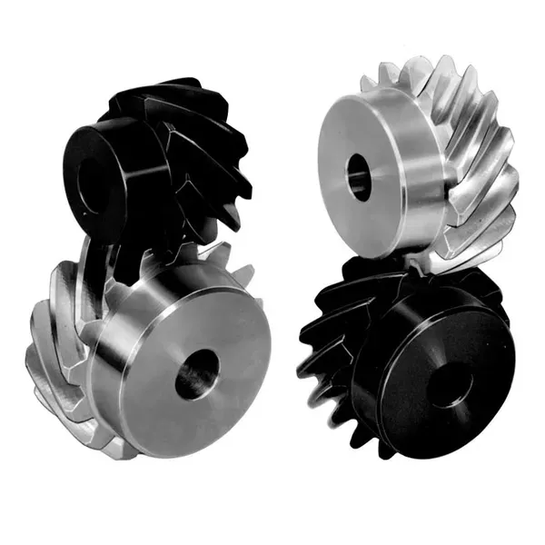
Related Product: High-Efficiency Spiral Bevel Gears
Australia Ever-Power’s spiral bevel gears are available with superfinishing and synthetic-oil-compatible surface treatments as standard options — the specification combination that delivers the highest measurable efficiency in single-stage bevel gear drives. Rated efficiency 97.5–98.5% per stage under correct installation and lubrication conditions.
Brand Comparison: Efficiency-Related Capabilities
Customer Feedback
“Switching to synthetic PAO on our 12 bevel gearboxes at the cement grinding station reduced electricity consumption by 1.8% measured over a three-month period. At our consumption level that is approximately AUD $42,000 per year — the oil upgrade paid back in six weeks.”
“Correcting the contact pattern on four bevel gearboxes that had been incorrectly shimmed at last overhaul (heel contact, not centred) was the cheapest efficiency improvement we have ever made. Two hours of maintenance labour per unit, zero parts cost, and a measured 1.3% input power reduction across the four drives.”
“Specified superfinished spiral bevel gears from Australia Ever-Power for our high-speed test rig drive. Efficiency improvement over ground-only gears was 1.8% at rated load — well within our prediction from the friction coefficient data. Four stars because delivery took a day longer than quoted.”
“The efficiency data from Australia Ever-Power for our sustainability report was exactly what we needed — specific efficiency values at rated load with superfinishing and PAO oil, compared to the baseline spec. Our ESG team used it directly for the NGER submission. That level of technical documentation is rare from a gear supplier.”
Frequently Asked Questions — Bevel Gear Efficiency
Maximise Your Bevel Gear Drive Efficiency
Australia Ever-Power | 27 Harley Crescent, Condell Park NSW 2200 | [email protected]