
The Question Every Gear Engineer Faces
When a project calls for a right-angle drive, the first decision after choosing bevel gears as the gear type is almost always: straight bevel or spiral bevel? It sounds like a simple question, but the engineering implications reach into noise levels, load capacity, manufacturing cost, bearing selection, and long-term reliability in ways that are far from trivial. Making the wrong choice — defaulting to straight bevel gears because they appear simpler, or over-specifying spiral bevel gears where they add cost without benefit — is a mistake that appears in many engineering projects across Australian industry.
Spiral bevel gears feature curved, oblique teeth that wrap around the conical pitch surface at a defined spiral angle — typically 35° in the Gleason standard. Straight bevel gears have teeth that run straight along the cone element, from the outer to the inner end, with no angular offset. That geometric difference produces a cascade of mechanical, acoustic, and manufacturing consequences that this article unpacks in full.
Australia Ever-Power, located in Condell Park NSW 2200, manufactures both gear types and supplies them across Australian mining, agriculture, marine, food processing, and industrial sectors. The comparisons in this article reflect genuine engineering experience — not catalogue marketing language.
How Spiral Bevel Gears Work: The Geometry Explained
The Curved Tooth Form and Its Mechanical Effect
The defining feature of a spiral bevel gear is its curved tooth — the tooth is cut at a mean spiral angle (ψm) to the pitch cone element, so that as the gear rotates, each tooth enters and leaves mesh progressively from one end of the face to the other rather than all at once. This progressive engagement is precisely what gives spiral bevel gears their acoustic and load-carrying advantages over straight bevel gears. Contact begins at one end of the tooth and sweeps smoothly across the full face width during each mesh cycle, distributing the load continuously rather than applying it as a sudden full-width impact.
The most widely used spiral angle is 35° (Gleason standard), which provides an excellent balance between face contact ratio improvement and axial thrust force generation. At 35°, the face contact ratio — the proportion of the mesh cycle during which multiple teeth are simultaneously in contact in the axial direction — is typically 1.4 to 1.8 depending on the face width and module. This means at any given instant, the tooth load is distributed across the equivalent of 1.4 to 1.8 tooth widths, reducing the peak stress at any single tooth by 30–45% compared to the equivalent straight bevel gear.
Total Contact Ratio: Why It Matters
The total contact ratio of a spiral bevel gear is the sum of the transverse contact ratio (how many tooth pairs are simultaneously engaged in the profile direction) and the face contact ratio (from the spiral overlap). A typical spiral bevel gear achieves a total contact ratio of 2.2 to 2.8, meaning between two and three tooth pairs carry the load at any instant. A straight bevel gear’s total contact ratio is purely transverse — typically 1.4 to 1.8 — so single-tooth contact occurs during a significant portion of each mesh cycle. It is during these single-tooth contact periods that the peak bending stress and contact stress are highest, and that acoustic impulses are generated.
Straight Bevel Gears: Strengths and Genuine Use Cases
Straight bevel gears should not be dismissed as simply “inferior” to spiral bevel gears — that framing misses the reality of their engineering value in specific applications. The straight tooth form makes straight bevel gears mechanically the simplest possible bevel gear: no net axial thrust force from tooth geometry (only from the tooth normal force component), no hand-of-spiral directionality requirement, straightforward form-milling manufacture on standard equipment, and easy interchangeability between mating pairs without matched-pair requirements. These properties make straight bevel gears the correct choice in a defined set of applications where their limitations are not relevant.
The most common straight bevel gear applications involve low-to-moderate speeds (pitch-line velocity below 5–8 m/s), relatively clean operating environments, moderate torque loads, and situations where first cost is more important than noise level or dynamic load performance. Agricultural PTO gearboxes, hand tool drives, low-speed conveyor corner drives, and instrumentation mechanisms all fall into this category. At these speeds, the acoustic difference between straight and spiral bevel gears is much less pronounced, and the manufacturing cost saving of straight bevel gears represents real value without meaningful performance penalty.
Mitre gears — a specific subset of straight bevel gears with 1:1 tooth ratio and 45° pitch cone angles on both gears — are widely used in machine tools, printing machinery, and instrumentation where a simple 90° direction change at equal speed is needed. The symmetrical geometry makes mitre gears fully interchangeable: any mitre gear of the correct module will mesh with any other mitre gear of the same module, regardless of which was the pinion and which was the wheel in the original application. This interchangeability simplifies spare parts management significantly.
Spiral vs Straight: A Direct Performance Comparison
| Performance Parameter | Spiral Bevel | Straight Bevel | Key Reason |
|---|---|---|---|
| Noise level (medium/high speed) | Low | Medium–High | Progressive vs sudden engagement |
| Load capacity (same size) | Higher | Lower | Higher contact ratio distributes load |
| Speed capability | Up to 40+ m/s | Best < 8 m/s | Dynamic load factor escalates with speed |
| Manufacturing cost | Higher | Lower | Gleason/Klingelnberg machines needed |
| Axial thrust force | Higher (spiral angle) | Lower | Spiral adds helical force component |
| Interchangeability | Matched pairs (lapped) | Full (same module) | Lapping creates pair-specific geometry |
| Efficiency (%) | 97–99% | 95–98% | Straight: more impact losses per cycle |
How Spiral Bevel Gears Are Manufactured
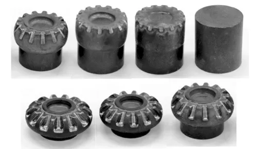
Conical blanks are forged from alloy steel (typically 8620, 9310, or 4340) with controlled grain flow aligned to the tooth direction, then rough-turned to the blank cone dimensions. Normalising or annealing relieves forging stresses before finish machining.
A rotating face-mill cutter head generates the spiral tooth form via simultaneous cutter rotation and blank generating roll motion. Machine settings (Gleason CAGE software) are calculated to produce the target contact pattern and spiral angle. First-off inspection confirms tooth geometry before production continues.
Gears are loaded into a carburising furnace at 900–950°C in a carbon-rich atmosphere. Carbon diffuses into the surface to a specified case depth (typically 0.8–1.6 mm). Gas quenching follows, achieving 58–62 HRC surface hardness while maintaining 38–44 HRC core toughness.
For AGMA Class 9–10: matched pairs are lapped together with abrasive compound to achieve Ra 0.4–0.8 µm and optimised contact pattern. For Class 11+: CNC gear grinding corrects post-hardening distortion to AGMA Class 11–12 accuracy independently on each gear.
Dimensional inspection (tooth profile, pitch, runout), contact pattern verification, backlash measurement, and surface roughness confirmation. Material certificates, hardness test records, and inspection reports issued with each gear set.
Where Spiral Bevel Gears Are Used: Real Industry Applications
Spiral bevel gears dominate any application where speed exceeds approximately 8 m/s pitch-line velocity, where noise is a constraint, or where maximum load capacity in a compact package is required. The automotive differential remains the archetypal application — virtually every passenger car, truck, and SUV with a driven rear axle uses a spiral bevel ring-and-pinion (or hypoid) set inside the differential housing. The 35° spiral angle, case-carburised 8620 steel, and lapped finish of a typical automotive differential gear set represents decades of refinement toward the lightest, quietest, most durable configuration possible at high production volumes.
In Australian mining operations, spiral bevel gear sets appear in conveyor drive heads, shearer cutting drum gearboxes, rotary drill rigs, and haul truck axle differentials. The combination of high torque loads, vibration, and contamination in these environments demands the structural advantage of spiral bevel gears — their higher contact ratio distributes shock loads across more tooth pairs simultaneously, reducing the risk of single-tooth fracture from a load spike. Ever-Power supplies mining-specification spiral bevel sets to Queensland and Western Australian operations with full material traceability documentation.
Aerospace represents the highest-performance end of the spiral bevel gear application spectrum. Helicopter main and tail rotor gearboxes operate spiral bevel stages at pitch-line velocities exceeding 40 m/s, transmitting thousands of kilowatts in packages that must survive for thousands of flight hours without failure. Materials here advance to aerospace-grade steels (AMS 6308, 9310) with superfinished tooth surfaces achieving Ra < 0.1 µm, and designs validated by comprehensive fatigue analysis to FAA/EASA certification standards.
Zerol Bevel Gears: The Middle Ground Option
Zerol bevel gears occupy an interesting technical middle ground between straight and spiral bevel gears. Like spiral bevel gears, they have curved teeth — but the mean spiral angle at the tooth midface is exactly 0°. The curved tooth form provides the smooth, progressive engagement of a spiral bevel gear while maintaining the zero net axial thrust characteristic of a straight bevel gear (the axial thrust from the tooth normal force cancels at the zero spiral angle condition). This combination makes zerol bevel gears specifically attractive in applications where bearing arrangements cannot accommodate significant axial thrust, but where smooth operation and low noise are still required.
Zerol bevel gears are manufactured on the same Gleason face-milling equipment as standard spiral bevel gears, but with a different machine setting that produces the curved tooth form at zero mean spiral angle. They are more expensive than straight bevel gears but generally less costly than full spiral bevel gears, since the zero spiral angle simplifies the machine settings and reduces tooling complexity. Applications include precision instrumentation, aircraft actuation systems, and medical equipment where smooth motion transmission with minimal axial load on delicate bearing arrangements is essential.
Price Comparison: Spiral vs Straight vs Zerol Bevel Gears
Indicative pricing (AUD) for Module 4 gear pairs, single-unit purchase. Contact [email protected] for current project quotations.
| Gear Type | AGMA Class | Price Range (AUD) | Best Suited For |
|---|---|---|---|
| Straight Bevel (form milled) | 7–8 | $180–$420 | Agriculture, low-speed machinery |
| Zerol Bevel (case-hardened) | 8–9 | $450–$900 | Instruments, actuation, medical |
| Spiral Bevel (lapped, Cl. 9–10) | 9–10 | $700–$1,400 | Automotive, industrial gearboxes |
| Spiral Bevel (CNC ground, Cl. 11) | 11 | $1,600–$3,200 | Mining, aerospace, precision drives |
| Spiral Bevel (superfinished, Cl. 12+) | 12–13 | $4,000–$10,000+ | Helicopter, F1, precision aerospace |
Materials for Spiral Bevel Gears: Selection Guide
Material selection for spiral bevel gears is more demanding than for straight bevel gears because the higher contact ratio concentrates Hertzian contact stress over a larger tooth area simultaneously, and the sliding action at the tooth contact (along the tooth length in the spiral direction) generates heat and lubricant film demands that require adequate surface hardness and oil film support. The standard choice for industrial spiral bevel gears is case-carburising alloy steel — grades 8620, 9310, 4320, or 18CrNiMo7-6 (European equivalent) — heat treated to achieve 58–62 HRC surface hardness over a 0.8–1.6 mm case depth with a 38–44 HRC tough core.
For corrosive environments such as marine, food processing, or chemical plant installations, Grade 316 stainless steel spiral bevel gears are available. Stainless steel cannot be case-carburised effectively, so surface hardness is limited to approximately 35–42 HRC through nitriding or through-hardening — reducing load capacity compared to case-carburised gears of the same size. For food-contact applications, the compliance with FSANZ and NSF H1 lubricant requirements typically outweighs the load capacity reduction, and the gear size is uprated accordingly.
Bronze alloy spiral bevel gears — while less common than their straight-bevel bronze counterparts — appear in low-load, noise-sensitive applications such as nautical instrument drives and precision measuring equipment. The inherent self-lubricating properties of leaded tin bronze allow operation with marginal lubrication, and the non-sparking characteristic matters in certain hazardous area classifications. Australia Ever-Power machines spiral bevel gears from bronze bar stock for specialist applications where corrosion resistance and non-sparking properties are both required.
Related Components for Spiral Bevel Gear Systems
Tapered Roller Bearings
Handle the combined radial and axial thrust loads generated by spiral tooth geometry. Preload setting is critical — determines contact pattern under operating load.
Precision Shim Packs
Control mounting distance and bearing preload to ±0.02 mm. Keeping a full range of shim thicknesses on hand enables correct assembly adjustment every time.
Gear Housing / Gearbox Casing
Rigidity of the housing determines whether shaft deflection under load shifts the contact pattern toward tooth ends. Distorted housings cannot be corrected by shimming alone.
Shaft Lip Seals
Primary barrier against lubricant loss and contamination ingress. Replace at every major overhaul — used seals are the leading cause of post-maintenance oil leaks.
EP Gear Oil (GL-4/GL-5)
Provides the extreme pressure additive film necessary at the sliding contact zone of spiral bevel tooth flanks. Grade ISO VG 220 is the most common specification.
Breather Vents
Equalise internal gearbox pressure during thermal cycling. Blocked breathers pressurise housing and force oil past shaft seals, causing contamination ingress and oil loss.
Australia Ever-Power vs Other Suppliers
When sourcing spiral bevel gears in Australia, the supplier landscape divides into offshore catalogue importers, local distributors without manufacturing, and specialist manufacturers. The differences are significant for quality-sensitive applications.
| Capability | Ever-Power | Import Agents | Local Distributors |
|---|---|---|---|
| Custom spiral bevel sets | ✓ Yes | ✗ No | ✗ No |
| Material certificates | ✓ Standard | ⚠ Variable | ✗ Rarely |
| AGMA Class 11 capability | ✓ Yes | ⚠ Limited | ✗ No |
| NSW-based technical support | ✓ Direct | ✗ Offshore | ⚠ Limited |
| Urgent lead time (< 4 weeks) | ✓ Available | ✗ 8–16 wks | ✗ Stock-limited |
Customer Reviews
“Replaced the OEM spiral bevel set in our haul truck differential with Ever-Power units. Same spec, better material documentation, and delivered in under three weeks to site in WA. Eighteen months in with zero issues.”
“We specified Class 11 spiral bevel gears for our marine winch upgrade. Ever-Power delivered with the full CMM inspection report — something every other Australian supplier said wasn’t possible at this lead time.”
“Our legacy machine used straight bevel gears. Ever-Power’s engineer explained exactly why switching to spiral bevel at our operating speed would be worth the additional cost. The noise reduction was immediately noticeable.”
“Zerol bevel gears for our medical imaging table drive — a very specific requirement. Ever-Power understood the zero-thrust requirement immediately and delivered stainless steel zerol gears within four weeks. Exceptional.”
Frequently Asked Questions
Source Spiral Bevel Gears from Australia’s Specialist
Australia Ever-Power · Condell Park NSW 2200 · Custom manufacture and precision supply of spiral, straight, and zerol bevel gears across all Australian industries.