
1.8–2.2
Spiral Face Contact Ratio
~1.0
Straight Bevel FCR
5 m/s
Straight Bevel PLV Limit
35°
Typical Spiral Angle
Table of Contents
02 — Tooth Geometry: What Changes Everything
03 — Contact Mechanics Under Load
04 — Load Capacity Comparison
05 — Noise & Vibration (NVH)
06 — Operating Speed Range
07 — Axial Thrust & Bearing Requirements
08 — Manufacturing & Cost
09 — Materials for High-Load Applications
10 — Full Head-to-Head Comparison Table
11 — Industry Applications by Type
12 — When Straight Bevel Gears Still Win
13 — Maintenance: Straight vs Spiral
14 — Price Comparison Table
15 — Sustainability & Compliance
16 — Case Studies
17 — Brand Comparison
18 — Customer Reviews
19 — FAQ
01
The Core Question — Why the Gear Tooth Form Matters Under High Load
Engineers selecting bevel gears for demanding drive applications face a recurring decision: straight bevel gear or spiral bevel gear? Both transmit torque between intersecting shafts. Both can be manufactured from the same materials to the same quality grades. But in terms of load capacity, fatigue life, noise performance, and high-speed capability, the two tooth forms are not equivalent — and under serious high-load conditions, the difference becomes significant enough to determine whether a gear set survives its design life or fails prematurely.
The short answer to the title question is: for the majority of high-load applications, spiral bevel gears are the superior choice. The reasons are rooted in contact mechanics — specifically in how the tooth contact ellipse forms and traverses the tooth face during meshing. But “the majority of high-load applications” is not all applications, and the engineering case for straight bevel gears in specific scenarios is genuine and economically meaningful. This article examines both tooth forms across every relevant technical parameter so that the choice for any given application can be made on the basis of evidence rather than assumption.
Australia Ever-Power designs, manufactures, and supplies both straight and spiral bevel gears from Condell Park NSW. The recommendation is always made on technical merit for the specific application — not on price or availability grounds.
Contact [email protected] to discuss which tooth form is appropriate for your load and speed requirements.
02
Tooth Geometry — The Single Most Important Difference
Straight Bevel Gear Tooth Form
In a straight bevel gear, each tooth runs radially along the pitch cone surface from the small end (toe) to the large end (heel), converging on the pitch cone apex. The tooth sides are straight lines in the plane of the pitch cone, and the tooth depth tapers proportionally from heel to toe (full-depth or Coniflex form). When a straight bevel gear tooth enters mesh with its mating gear, the entire tooth face width contacts the mating tooth simultaneously — the contact line snaps from zero to full face width instantaneously at each tooth engagement event. This abrupt full-width contact produces a characteristic impulse load at the mesh frequency that is the source of the tapping or knocking noise associated with straight bevel gears at speed, and is the fundamental reason for their lower fatigue resistance compared to spiral bevel gears at equivalent load and speed.
Spiral Bevel Gear Tooth Form
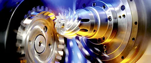
In a spiral bevel gear, each tooth follows a curved spiral arc across the face width, with the tooth making an oblique angle — the spiral angle, typically 35° for standard production gears — to the pitch cone element. When a spiral bevel gear tooth enters mesh, contact begins at one end of the tooth and progresses smoothly across the face width as the gears rotate, before contact ends at the opposite end. This progressive engagement — the defining mechanical advantage of the spiral form — transforms the instantaneous full-width contact of the straight bevel gear into a continuously moving contact ellipse that sweeps across the tooth surface. The contact ellipse is never larger than the tooth face at any instant, the load builds and releases gradually, and the dynamic impact component that causes noise and fatigue damage in straight bevel gears is substantially reduced.
The Face Contact Ratio — Quantifying the Difference
The face contact ratio (FCR) is the numerical expression of how many tooth pairs are simultaneously in contact as the gears mesh. For straight bevel gears, FCR ≈ 1.0–1.2 — at most one to 1.2 tooth pairs in simultaneous contact. For spiral bevel gears at a 35° spiral angle, FCR = 1.8–2.2 — between 1.8 and 2.2 tooth pairs sharing the load at any instant. This 80–100% increase in the number of load-sharing tooth pairs directly translates into reduced contact stress per tooth pair, reduced bending stress at the tooth root, lower transmission error (smoother speed delivery), and consequently longer fatigue life. The face contact ratio is the single most important parameter explaining why spiral bevel gears handle high loads better than equivalent-size straight bevel gears.
03
Contact Mechanics Under High Load — Hertz Stress and Fatigue
Hertzian Contact Stress
Bevel gear tooth surfaces in contact deform elastically under load — the contact is not an ideal mathematical line or point, but a finite-area ellipse whose dimensions and peak pressure are governed by Hertzian contact mechanics. The Hertz contact pressure is inversely related to the contact area: a larger contact ellipse (from the spiral bevel’s progressive engagement and higher FCR) distributes the load over a larger surface, reducing the peak contact stress. A smaller or narrower contact zone (as in the straight bevel’s full-width instantaneous line contact at lower FCR) concentrates load onto less material, producing higher peak contact stress. The contact fatigue life of a gear tooth is a function of the cube or higher power of the contact stress — a 20% reduction in contact stress can double or triple the pitting fatigue life. The spiral bevel gear’s consistently lower contact stress under the same transmitted load is the primary reason for its superior contact fatigue life.
Bending Fatigue at the Tooth Root
The tooth root bending stress — the tensile stress at the fillet between the tooth and the gear body, which is the initiation site for tooth root fatigue cracks — is also lower in spiral bevel gears for any given transmitted torque. The higher FCR means the instantaneous bending load on any single tooth is reduced by the load-sharing factor. Additionally, the oblique tooth contact in a spiral bevel gear produces a more favourable stress distribution along the tooth root compared to the straight tooth form. Shot peening of the tooth root fillet — standard practice for case-hardened spiral bevel gears in demanding applications — introduces compressive residual stresses that further extend bending fatigue life. The combination of lower instantaneous load per tooth and beneficial stress distribution gives spiral bevel gears approximately 1.5–2.0× the bending fatigue life of equivalent straight bevel gears under the same load conditions.
Shock Load Absorption
Under shock loading — the instantaneous torque spikes characteristic of mining, agricultural, and heavy industrial applications — the spiral bevel gear’s progressive tooth engagement provides a natural shock absorption mechanism. The gradual build-up of contact as the tooth enters mesh distributes the shock energy over a finite time and face-width distance, rather than absorbing it entirely at the instant of tooth engagement as a straight bevel gear does. For applications subject to frequent shock loads (ore surge in conveyor drives, crop ingestion in agricultural PTO drives, clutch engagement shocks in mobile plant), the spiral form’s shock resistance provides a meaningful service life advantage that a simple static load comparison does not capture.
04
Load Capacity Comparison — By the Numbers
The AGMA gear rating standard (AGMA 2003) provides a quantitative framework for comparing the rated load capacities of bevel gear types. For two gear sets of identical geometry — same module, tooth count, face width, material, and quality grade — the spiral bevel gear set consistently achieves a higher allowable tangential load (and therefore higher rated power at any given speed) than the straight bevel equivalent. The ratio of spiral-to-straight rated load capacity, at the same geometry and quality, is typically in the range of 1.3–1.8, depending on speed, module, and application service factor.
⚙️ Straight Bevel Gear — Load Profile
- Contact fatigue limit: moderate (full-width line contact)
- Bending fatigue: adequate for low-to-medium loads
- Shock load tolerance: limited — abrupt tooth engagement
- FCR: 1.0–1.2 — minimal multi-tooth sharing
- Suitable continuous load: typically up to ~60% of equivalent spiral bevel rating
- Speed limit: 5 m/s PLV for acceptable noise/vibration
🌀 Spiral Bevel Gear — Load Profile
- Contact fatigue limit: high (distributed Hertz ellipse)
- Bending fatigue: 1.5–2.0× straight bevel at same geometry
- Shock load tolerance: good — progressive engagement absorbs shock
- FCR: 1.8–2.2 — sustained multi-tooth load sharing
- Continuous load: full AGMA rated capacity utilised
- Speed range: practical to 40+ m/s PLV with correct lubrication
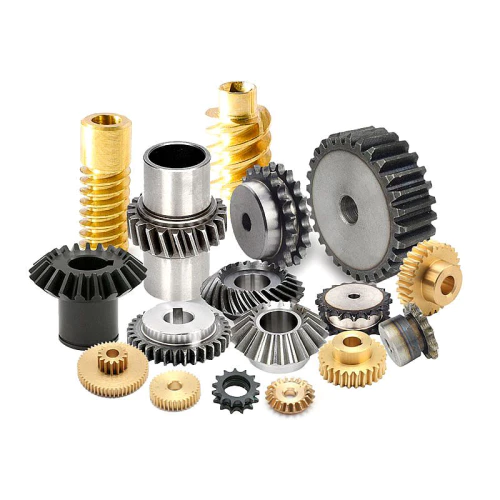
In concrete terms: if the application requires maximum load in minimum gear size, spiral bevel gears are almost always the answer. For a given rated power and speed, a spiral bevel gear set is physically smaller than an equivalent-rated straight bevel gear set — the better contact mechanics allow more power to be transmitted through less material. This size advantage compounds in systems with tight envelope constraints: mining conveyor head drives, CNC machine tool spindle gearboxes, and marine Z-drive lower units all benefit directly from the spiral bevel’s higher power density.
05
Noise and Vibration — The NVH Argument for Spiral Bevel Gears
Noise, vibration, and harshness (NVH) performance is one of the most decisive differentiators between straight and spiral bevel gears under any load condition, and the difference is especially pronounced at elevated speeds and loads. The mechanism is straightforward: in a straight bevel gear, each tooth engagement event produces a step change in the transmitted force — the load jumps from zero to full in one instant as the tooth enters contact, and drops back to zero equally abruptly when it leaves. This impulsive force variation at the gear mesh frequency generates a strong vibration signal that propagates through the gear housing into the machine structure and radiates as airborne sound.
In a spiral bevel gear, the progressive engagement produces a force variation that builds and decays smoothly — a near-sinusoidal force history at the tooth mesh frequency rather than a square-wave impulse. The harmonic content of this smoother force signal is fundamentally different: the dominant mesh frequency component is present in both gear types, but the spiral bevel’s smooth engagement suppresses the higher harmonics that are responsible for the harsh, penetrating character of straight bevel gear noise at speed. Transmission error — the deviation of the output shaft from perfectly uniform rotation, which is the root cause of gear noise — is significantly lower for spiral bevel gears than for straight bevel gears at the same mesh frequency.
In quantitative terms, the NVH improvement from switching from a straight to a spiral bevel gear set in the same application typically ranges from 8–15 dB(A) at the gear mesh frequency — an audible improvement that corresponds to a perceived loudness reduction of approximately half to one quarter. For occupational noise compliance in Australian workplaces (the Work Health and Safety Regulation 2017 sets the 8-hour exposure limit at 85 dB(A)), this improvement can be the difference between compliance and a requirement for additional noise control measures.
Above 5 m/s pitch line velocity, straight bevel gears are generally not suitable for continuous operation on noise grounds alone — the impulse loading at higher mesh frequencies produces structural resonance and accelerated fatigue damage at gear mesh harmonics, in addition to the audible noise problem. Spiral bevel gears are designed to operate continuously at pitch line velocities up to 40 m/s and beyond with appropriate lubrication and housing design — there is no equivalent noise-related upper speed limit for the spiral tooth form.
06
Operating Speed Range — Where Each Type Is at Home
Speed range is one of the clearest boundaries in the straight vs spiral bevel selection decision, and it correlates directly with the noise and fatigue mechanisms described above.
Low Speed: 0 – 5 m/s PLV
Both straight and spiral bevel gears are mechanically acceptable here. Straight bevel gears are typically preferred in this range for cost reasons — simpler manufacturing, lower tooling requirements, and adequate performance for the load. Examples: agricultural PTO drives, hand tool gearboxes, valve actuators, low-speed auxiliary machinery.
Medium Speed: 5 – 20 m/s PLV
Spiral bevel gears are the standard specification in this range. Straight bevel gears at these speeds produce unacceptable noise and have substantially shortened fatigue life due to the impact loading at each tooth engagement. Industrial gearboxes, CNC machine tool drives, moderate-speed conveyor drives, marine sterndrive lower units — all standard spiral bevel territory.
High Speed: 20 – 40+ m/s PLV
Spiral bevel gears only, at AGMA 12–13 quality, with forced-circulation lubrication systems, precision-balanced gear sets, and rigidly designed housings. Straight bevel gears are not used in this speed range under any circumstances. Aerospace gearboxes, high-speed turbine accessories, helicopter transmission stages.
07
Axial Thrust and Bearing Requirements — The Price of the Spiral
⚠️
Critical Design Point: Axial Thrust in Spiral Bevel Gears
Spiral bevel gears generate significant axial thrust loads on both the gear and pinion shafts — loads that do not occur at the same magnitude in straight bevel gears. These thrust loads must be absorbed by correctly sized and preloaded tapered roller bearings. Failing to design for axial thrust results in rapid bearing failure. This is not a reason to avoid spiral bevel gears — it is a design requirement that must be accounted for in the bearing and housing design.
The source of axial thrust in spiral bevel gears is the oblique tooth contact angle — the same spiral angle that produces progressive engagement also generates a force component along the tooth spiral direction, which resolves into a net axial force on each shaft. The magnitude of this thrust depends on the spiral angle, the transmitted torque, the gear ratio, and whether the gear hand (left or right-hand spiral) is chosen to produce a “separating” or “converging” thrust relative to the mesh point.
In a well-designed spiral bevel gear installation, the axial thrust loads are calculated as part of the bearing design process. Tapered roller bearings — the standard bearing type for bevel gear shafts — are rated for combined radial and axial loads and are entirely capable of handling the axial thrust from spiral bevel gears, provided they are correctly selected and preloaded. The preload setting is critical: excessive preload generates heat; insufficient preload allows axial float that shifts the contact pattern off-centre and degrades gear performance.
Straight bevel gears do generate some axial thrust (from the taper geometry of the pitch cone), but the magnitude is substantially lower than in spiral bevel gears at the same transmitted load. This is one genuine mechanical advantage of the straight bevel form: the bearing design is simpler and the bearing loads are lower. However, for most industrial applications, the engineering complexity of handling spiral bevel axial thrust is entirely manageable and is far outweighed by the load capacity, noise, and speed benefits.
08
Manufacturing Process and Cost Comparison
Straight Bevel Gear Manufacturing
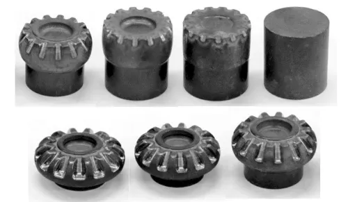
Straight bevel gears are cut by Coniflex-style twin-blade face milling or by form-milling processes on relatively simple machine tools. The cutting geometry is straightforward — the tool moves in a straight path across the tooth space — and the machine setup is less complex than for spiral bevel cutting. This simplicity translates into lower tooling cost, shorter setup time, and the ability to produce straight bevel gears on a wider range of machine tools, including conventional gear milling machines that cannot cut spiral bevel tooth forms. For small production quantities or for large module (M12+) straight bevel gears where CNC spiral cutting would be expensive, the manufacturing cost advantage of the straight form is significant.
Spiral Bevel Gear Manufacturing
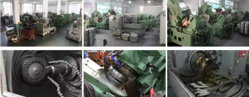
Spiral bevel gears require CNC face-milling or face-hobbing machines (Gleason Phoenix, Klingelnberg Palladion, or equivalent platforms) with multi-axis simultaneous CNC capability to generate the curved tooth form from digital tooth files. The bevel gear cutter tools — circular face-mill cutter heads with carbide insert blades — are more complex and more expensive to produce and maintain than straight bevel cutting tools. Machine setup requires generation of the complete tooth file from the gear design parameters, which demands specialist knowledge and software. However, once a CNC bevel gear cutting machine is set up for a given gear design, it produces parts to consistent quality with minimal operator intervention, and the production rate for small-to-medium module gears is entirely competitive with straight bevel production in volume.
Hard Finishing: Lapping vs Grinding
Both straight and spiral bevel gears can be finish-hardened and then either lapped (run together with abrasive compound) or ground. Straight bevel gears are less commonly ground than spiral bevel gears — the simple tooth form is more amenable to post-hardening form grinding, but the lower performance requirements of most straight bevel applications make this extra step unnecessary and uneconomical. Spiral bevel gears are routinely gear-lapped (producing a matched pair that must stay together in service) or CNC profile-ground (achieving AGMA 12–13 quality, allowing individual gear replacement). The grinding route adds cost but eliminates the matched-pair constraint and achieves tighter dimensional tolerances that improve NVH performance.
09
Bevel Gear Materials for High-Load Applications
High-load bevel gear applications use essentially the same material specifications regardless of whether straight or spiral tooth form is chosen — the dominant material for both is case-hardened alloy steel, with the specific grade and quality level selected to match the load severity. The table below shows the standard material progression for increasing load demand.
10
Full Head-to-Head Technical Comparison
★ For high-load applications, spiral bevel gears are the standard recommendation across all parameters except manufacturing cost and axial thrust complexity.
11
Industry Applications by Gear Type
Understanding which applications use which tooth form in practice provides the clearest real-world picture of where the performance boundaries lie.
⛏️ Mining & Resources (Australia)
Spiral bevel (dominant): Overland conveyor right-angle drive heads, longwall shearer cutting drives, mill drives. High continuous load, shock loading from ore surges, 24/7 operation.
Straight bevel (limited): Some low-speed auxiliary drives, walkways, inspection hatches. Where load is genuinely light and cost is the primary driver.
🚗 Automotive & Transport
Spiral bevel / hypoid (standard): Rear axle differentials since the 1940s. Transfer case stages, front differential drives in AWD systems. High speed, sustained load, millions of km service life.
Straight bevel: Spider gears and side gears inside the differential carrier. Very low relative speed (only active during wheel speed differential) so straight tooth form is adequate here.
✈️ Aerospace & Defence
Spiral bevel exclusively: Helicopter main and tail rotor gearboxes, aircraft accessory drives, military vehicle final drives. Maximum power density, zero tolerance for noise or failure.
Straight bevel: Not used in primary aerospace power transmission. Possibly in very low-power instrument and avionics drives only.
🌾 Agriculture
Spiral bevel: High-power combine header drives, large forage harvester drives, premium tractor PTO drives. Demanding duty cycles, significant shock loading.
Straight bevel: Standard tractor PTO auxiliary drives, mower drives, low-speed implement drives. Cost-sensitive, intermittent duty, modest loads. Remains the majority tooth form in agricultural implements.
🤖 Robotics & CNC
Spiral bevel / zerol bevel: Robot wrist joints, CNC spindle angle drives, high-speed automation. AGMA 12–13, low backlash, high positional accuracy required.
Straight bevel: Occasional use in slower automation axes where backlash and positional accuracy requirements are modest. Generally not the preferred choice in robotics.
🌊 Marine & Offshore
Spiral bevel: Outboard lower units, sterndrive Z-drives, azimuth thruster drives, ROV thrusters. Continuous operation, sealed housing, wide temperature range, corrosion resistance required.
Straight bevel: Marine steering gear (low speed, intermittent), some manual valve actuators on offshore platforms.
Featured Product
Spiral Miter Bevel Gear — Precision 1:1 Spiral Tooth Form
The quieter, longer-lasting alternative to straight mitre gears for food processing, automation and packaging line directional drives.
12
When Straight Bevel Gears Still Win — Honest Assessment
Recommending spiral bevel gears for high-load applications is technically correct, but it would be dishonest to imply that straight bevel gears have no valid role. There are genuine scenarios where straight bevel gears are the better engineering and commercial choice:
Low PLV + Low Load + Cost Priority
Agricultural implement drives, hand tool gearboxes, valve actuators, and low-speed auxiliary drives where PLV is consistently below 3 m/s and loads are light-to-medium. The spiral bevel’s performance advantages are not utilised at these operating conditions, and the cost premium is not justified.
Large Module, Low Volume
Very large module (M12+) bevel gears for mining and process plant applications at low speed. At these sizes and small production quantities, the CNC spiral bevel cutting machine setup cost per piece can exceed the load-performance benefit. Straight bevel at large module may be more economical if the speed is low enough.
Bearing System Simplicity Required
In some retrofit or replacement applications where the existing housing and bearing positions are fixed and cannot accommodate the thrust loads of a spiral bevel gear set without significant modification, a straight bevel replacement is more practical if the load and speed are within the straight bevel’s capability.
Quick Lead Time on Standard Sizes
Standard straight bevel gears in common module/ratio combinations are often available from local stock with zero manufacturing lead time. For emergency replacements in applications that are within the straight bevel performance envelope, getting a straight bevel gear installed today may be more valuable than waiting two weeks for a spiral bevel set.
The key principle: evaluate whether your actual operating speed and load genuinely require the performance of a spiral bevel gear. If the PLV is below 4 m/s and the load is well within the straight bevel’s capability, the additional cost of a spiral bevel set delivers no measurable benefit and is not justified. If the PLV is above 5 m/s or the load is at the upper end of the gear set’s capacity, spiral bevel is the correct choice.
13
Maintenance Practices — Straight vs Spiral Under Operating Conditions
The maintenance requirements for straight and spiral bevel gears are similar in most respects — both require regular lubrication checks, periodic oil changes, seal inspection, and bearing condition monitoring. The differences lie in a few specific areas where the distinct tooth contact mechanics create different maintenance priorities.
Contact pattern inspection is more critical and more informative for spiral bevel gears than for straight bevel gears. The position and shape of the contact ellipse on a spiral bevel gear tooth surface — checked with marking compound during assembly and at major overhauls — reveals misalignment, housing distortion, bearing wear, and shim setting errors that may not yet be causing obvious symptoms. A contact ellipse that has migrated to the tooth heel or toe under load indicates a mounting distance or cone distance error that will shorten gear life significantly if uncorrected. Straight bevel gear contact patterns are less sensitive to this kind of migration and are more forgiving of minor misalignment.
Matched pair replacement is a critical maintenance rule for lapped spiral bevel gear sets — ring gear and pinion must always be replaced together. Straight bevel gears, which are not lapped as matched pairs, can sometimes be individually replaced if the mating gear is within tolerance. This is a genuine maintenance cost advantage for straight bevel gears in applications where tooth wear is uneven between gear and pinion.
Lubrication and contamination affect both types equally — both require the correct EP gear oil at the right level, and water contamination or abrasive particles in the oil destroy both types at similar rates. Synthetic gear oils with better viscosity-temperature characteristics and improved EP protection are recommended for both types in demanding duty applications, particularly in the temperature extremes common in Australian mining and agricultural environments.
14
Price Comparison — Straight Bevel vs Spiral Bevel (AUD)
The table below compares indicative AUD prices for straight and spiral bevel gear pairs at equivalent module and ratio specifications, with full material certification, at a quantity of 10 pairs. These are representative ranges — actual pricing depends on bore specifications, quality grade, delivery timeframe, and quantity.
Indicative AUD pricing at qty 10 pairs, AISI 8620/9310 case-hardened, with full material certs. Spiral bevel prices assume AGMA 11 lapped pair. Contact [email protected] for application-specific quotations.
The spiral bevel premium is consistently approximately 2× over an equivalent-specification straight bevel gear set. This premium is the manufacturing and tooling cost of the CNC spiral cutting process. When evaluating whether the spiral bevel is worth the premium in your application, consider that the spiral bevel gear set may provide 1.5–2.0× the service life at the same load — meaning the total cost of ownership over the gear set’s service life may actually be lower for the more expensive spiral set if the load and speed conditions place the straight bevel near its fatigue limit.
15
Sustainability, Global Markets & Regulatory Compliance
Both straight and spiral bevel gears are produced from steel alloys with well-established global recycling infrastructure. The additional manufacturing energy consumed in producing a spiral bevel gear set (CNC multi-axis cutting, more complex heat treatment management, lapping or grinding) is typically 20–40% greater than for an equivalent straight bevel gear set. However, when the longer service life of the spiral bevel set is factored in — particularly in high-load applications where the straight bevel set might require 2–3 replacements for every one spiral bevel set replacement — the lifecycle embodied energy of the spiral set is often lower per hour of service delivered.
In terms of market geography, straight bevel gears are produced and consumed predominantly in agricultural equipment manufacturing (dominant in the USA, Brazil, India, Australia, and Europe), light industrial machinery, and hand tools. Spiral bevel gears are the standard in the automotive industry (global production concentrated in USA, Germany, Japan, South Korea, and China), industrial gearbox manufacturing (Germany, USA, Japan), and aerospace (USA, UK, France). Australia is primarily a consuming market for both types, with the mining resources sector, automotive aftermarket, and agricultural machinery market representing the dominant domestic demand streams.
From a compliance perspective, the selection of straight vs spiral bevel gears does not in itself create specific regulatory obligations beyond those applying to mechanical power transmission components generally. However, for noise compliance under Australian workplace health and safety regulations, spiral bevel gears in noise-sensitive installations offer a practical tool for reducing gear drive noise without engineering or administrative controls — a compliance benefit that has real value for employers managing occupational noise exposure. Australia Ever-Power can provide application-specific noise estimates and compliance documentation support for customers undertaking noise assessments under the Work Health and Safety Regulations.
16
Case Studies — Real Decisions Between Straight and Spiral
CASE 01 — MINING, WA
Straight-to-Spiral Upgrade Eliminates Annual Gear Failure
A Goldfields conveyor drive had been using straight bevel gears in a right-angle drive head at 7 m/s PLV. Failures were occurring every 11–14 months from contact fatigue and noise-related vibration. Australia Ever-Power identified the PLV as above the straight bevel’s practical speed limit and supplied an AISI 9310 case-hardened spiral bevel replacement set at AGMA 11. The drive has operated for 36 months without gear-related failure. The 2× unit cost of the spiral set was recovered within 8 months in eliminated failure costs.
Outcome: Failure eliminated. Life tripled. ROI in 8 months.
CASE 02 — AGRICULTURE, SA
Straight Bevel Correctly Retained for Low-Speed PTO Auxiliary Drive
An SA grain grower replaced straight bevel gears in a PTO-driven grain auger drive annually and asked Australia Ever-Power whether a spiral bevel upgrade would help. Analysis showed the PLV was 2.1 m/s, load was light, and the annual failures were due to incorrect lubrication grade (GL-4 instead of GL-5 due to purchaser confusion). Recommendation: retain straight bevel gears, correct lubricant specification. Replacing lubricant eliminated the failures at zero additional gear cost.
Outcome: Correct diagnosis saved customer from unnecessary spiral bevel upgrade cost.
CASE 03 — FOOD PROCESSING, VIC
Spiral Miter Upgrade Reduces Conveyor Noise by 11 dB(A)
A Victorian meat processing facility had occupational noise levels in the conveyor processing area of 93 dB(A) — 8 dB above the regulatory exposure limit. Noise mapping identified straight bevel mitre gears in the conveyor right-angle drives as the primary source. Australia Ever-Power supplied 316L stainless spiral mitre gear sets in IP69K housings. Post-installation noise measurement: 82 dB(A) — an 11 dB(A) reduction that brought the facility within regulatory compliance without the cost of additional acoustic enclosures.
Outcome: 11 dB(A) noise reduction. Regulatory compliance achieved. Acoustic enclosures not required.
17
Brand Comparison — Australia Ever-Power vs Alternative Suppliers
In the Australian bevel gear supply market, customers choosing between straight and spiral bevel gears are also choosing between supply models. The table below compares the four principal supply models on the dimensions that matter most for engineering and maintenance buyers.
Australia Ever-Power’s key competitive advantage in the straight vs spiral decision is the availability of genuine engineering advice — not just a catalogue. When a customer is uncertain whether the performance benefits of a spiral bevel set justify the cost premium for their specific load and speed conditions, the Ever-Power engineering team can perform a quantitative load analysis, calculate the expected service lives for both options, and provide a total cost of ownership comparison. This service is not available from generic importers and is often limited to regional distributors when dealing with international premium brands.
18
Customer Reviews
“Our mining drive was running straight bevel gears and failing every year at a PLV of 8 m/s. Ever-Power explained clearly why the speed was the problem, not the material. Switched to spiral bevel, now 3 years without failure. The engineering explanation made it easy to justify the cost to management.”
— Robert Dalgety
Asset Reliability Engineer, Iron Ore Processing, WA
“Asked Ever-Power whether I should upgrade my agricultural PTO drives to spiral bevel. They honestly told me no — my PLV was too low to benefit. Saved me from spending money I didn’t need to. That kind of advice builds trust. I’ll be back for the drives that do need upgrading.”
— Owen Strickland
Farm Manager & Plant Owner, Riverina NSW
“Replaced straight bevel mitre gears in our conveyor line with Ever-Power spiral mitre gears. The difference in noise was immediately noticeable on the floor — our workers actually commented on it without being asked. Noise reduction was measured at over 10 dB. Worth every cent of the premium.”
— Michelle Carvalho
WHS Manager, Food Processing Facility, QLD
“CNC machine tool spindle angle drive required a very quiet, high-speed spiral bevel gear set at AGMA 12 quality. Ever-Power sourced and supplied within 10 days from their manufacturing partner network. Contact pattern documentation was exactly what our quality department needed. Slight delay from initial quoted lead time — hence 4 stars — but the product quality was excellent.”
— Thomas Krentz
Production Engineer, CNC Machine Tools OEM, VIC
19
FAQ — Straight Bevel vs Spiral Bevel Gears
Frequently asked technical and selection questions answered by Australia Ever-Power.