Why Contact Pattern Is the Assembly Quality Indicator
A bevel gear set can pass every dimensional inspection — tooth profile within tolerance, correct module, correct tooth count, backlash within specification — and yet still fail within months of operation because the tooth contact pattern is wrong. The contact pattern reveals something that individual dimensional measurements cannot: where the two tooth surfaces actually touch during mesh, and how that contact zone is distributed across the tooth face.
A correctly positioned contact zone, centred on the tooth midface at mid-tooth height, distributes the transmitted load evenly across the designed contact area. An incorrectly positioned contact zone — shifted toward the tooth ends, concentrated on the tooth tip or root, or misaligned with the tooth profile — concentrates the full load onto a fraction of the design area. The resulting stress concentration dramatically increases contact fatigue rate, accelerates surface pitting, and reduces gear life to a fraction of the designed value even if every other aspect of the application is correctly managed.
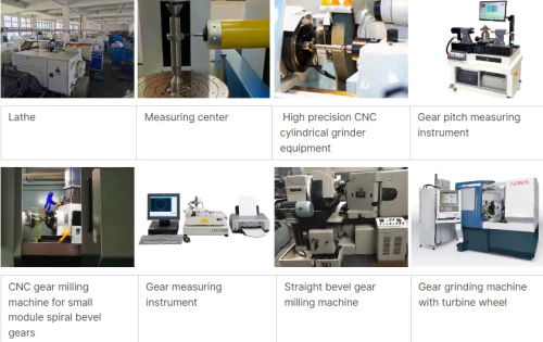
Australia Ever-Power in Condell Park NSW 2200 verifies contact patterns on all manufactured bevel gear sets before shipment and provides contact pattern photographs with delivery documentation. Our engineering team also assists customers with contact pattern interpretation and correction procedures through our technical support service at [email protected].
Equipment Required for Contact Pattern Testing
🔵 Engineer’s Blue (Marking Paste)
Prussian blue marking compound — thin consistency allows clear transfer to the mating tooth. Thick paste is too viscous and produces misleading oversized contact patterns. Apply a thin, even coat.
🖌️ Stiff Bristle Brush
For applying engineer’s blue to tooth flanks in a thin, consistent layer. A foam brush or cotton swab also works for smaller gears. Aim for film thickness ≤ 0.02 mm.
💡 Strong Light Source
LED inspection light for clear visibility of the transferred pattern. The contrast between the blue transfer on the clean tooth surface must be clearly readable to make confident diagnoses.
📷 Camera or Phone Camera
Photograph the pattern immediately after the test for documentation and comparison with specification patterns. Keep photographic records of each assembly for future reference.
📐 Dial Indicator and Magnetic Base
For measuring backlash simultaneously with contact pattern — the two tests are always performed together as both inform mounting distance accuracy.
🔧 Shim Stock and Shim Packs
Precision shims for adjusting mounting distances during pattern correction. Pre-prepared sets of 0.05, 0.10, 0.15, 0.20, 0.25, and 0.50 mm shims allow rapid adjustment trials.
Step-by-Step Contact Pattern Testing Procedure
Remove all oil, grease, and grit from the tooth flanks of both gears using solvent or brake cleaner. Any lubricant residue will prevent the marking compound from transferring cleanly and will produce a misleadingly large, indistinct pattern. The tooth surfaces must be completely clean and dry before applying marking compound.
Apply a thin, even coat of engineer’s blue to 6–10 consecutive teeth on the ring gear drive flank (the concave face for a spiral bevel ring gear). The layer should be thin enough that the tooth surface texture is still visible through the coating — approximately 0.01–0.02 mm thick. Too thick a coat produces an oversized pattern that masks the actual contact boundary.
Assemble the gear set in its housing with bearings and shims at their current setting. Apply light braking resistance to the ring gear by hand (simulate a light load). Rotate the pinion shaft through 2–3 full ring gear revolutions in the drive direction, then reverse through 1 revolution. The resistance is critical — rotating under zero resistance produces a pattern that is too small and unrepresentative of the loaded condition.
Disassemble to access the pinion teeth (or use an inspection port if available). The marking compound will have transferred from the ring gear teeth to the pinion tooth flanks where contact occurred, creating a blue impression on the clean pinion surface. This transfer pattern shows precisely where the tooth contact is occurring — its position in the tooth height direction (tip, pitch line, or root), its position in the face width direction (toe, midface, or heel), and its overall shape and coverage percentage.
Photograph 3–4 consecutive pinion teeth showing the pattern clearly. Note the pattern position: is it centred on the tooth face, or shifted toward heel/toe? Is it centred in the tooth height, or shifted toward tip/root? Estimate the percentage of tooth face area covered. Compare against the acceptance criteria (see pattern interpretation table below) and determine whether adjustment is required before proceeding.
If the pattern requires correction, adjust the appropriate shim pack (pinion mounting distance shim or ring gear bearing shim), clean the teeth completely, reapply marking compound, and repeat steps 3–5. Continue iterating until the pattern meets acceptance criteria. Document the final shim pack configuration and backlash measurement for assembly records.
Contact Pattern Interpretation: What Each Shape Means
Appearance: Oval or elliptical shape, centred on the tooth midface (between heel and toe), centred at the pitch line (between tip and root). Covers 40–65% of total tooth flank area. Edges are clear and well-defined.
Meaning: Correct mounting distances. Gear set will operate with distributed load, low noise, and full design life potential. Accept and proceed to bearing preload and final assembly.
Appearance: Pattern is shifted toward the large-diameter (heel) end of the tooth, with little or no contact visible at the small (toe) end.
Cause & Correction: Pinion is too close to ring gear centreline (mounting distance too small) OR ring gear is too far from pinion (ring gear mounting distance too large). Move pinion away from ring gear (increase pinion mounting distance shim thickness).
Appearance: Pattern concentrated at the small-diameter (toe) end of the tooth, absent or very light at the heel end.
Cause & Correction: Pinion is too far from ring gear centreline (mounting distance too large). Move pinion toward ring gear (reduce pinion mounting distance shim thickness). Toe contact is less load-critical than heel contact because toe teeth are smaller, but still causes stress concentration and should be corrected.
Appearance: Contact concentrated at the tooth tip (addendum), absent at the root. Pattern appears as a band along the top edge of the tooth profile.
Cause & Correction: Ring gear is too close to pinion — backlash too small. Increase ring gear mounting distance (move ring gear away from pinion). Tip contact is mechanically dangerous because the tooth tip has the least material and the stress concentration is highest — correct before operation.
Appearance: Contact concentrated at the tooth root, absent at the tip. Pattern appears as a band along the tooth root fillet.
Cause & Correction: Backlash too large — ring gear too far from pinion. Move ring gear toward pinion (reduce ring gear mounting distance). Root contact concentrates stress at the highest bending moment point — the risk of tooth fracture is elevated. Correct immediately.
Appearance: Contact zone appears at two separate areas on the tooth flank, or runs diagonally across the tooth in a way that suggests the two mating tooth surfaces are not conjugate.
Cause: Incorrect gear set (tooth depth system mismatch, wrong manufacturing method, or lapped pair separated and reassembled with wrong mating gear). Cannot be corrected by shimming — the gear set itself must be re-evaluated.
Pattern Correction Quick Reference
Summary of adjustments — “in” means toward the centreline, “out” means away from centreline.
| Pattern Problem | Move Pinion | Move Ring Gear | Effect on Backlash |
|---|---|---|---|
| Heel contact | OUT (away) | IN (toward) | Increases if pinion moved out |
| Toe contact | IN (toward) | OUT (away) | Decreases if pinion moved in |
| Tip contact | No change | OUT (away) | Increases backlash |
| Root contact | No change | IN (toward) | Decreases backlash |
Backlash Measurement and Acceptable Limits
Backlash measurement is performed simultaneously with contact pattern checking because both are consequences of the mounting distances and both must be acceptable before the assembly is confirmed. Backlash is measured at the ring gear midface, at the pitch radius, with a dial indicator set tangentially against a ring gear tooth while the pinion is held stationary. The indicator reading as the ring gear is rocked in both directions gives the circumferential backlash jt.
Typical Acceptable Backlash Ranges by Module (ISO 10300 reference):
These values apply to standard industrial applications at moderate temperatures. Applications with significant temperature variation during operation (where thermal expansion changes the effective mounting distance) require wider backlash to prevent gear seizure when the housing and shaft expand differentially with temperature. For high-temperature applications (gearboxes adjacent to furnaces, engines, or process heat sources), consult the gear manufacturer for thermally-adjusted backlash recommendations.
Customer Experiences with Contact Pattern Inspection
“A contractor rebuild our bevel gearbox and it ran noisily from day one. We used this exact guide — the contact pattern test showed heavy heel contact. Adjusted the pinion shim by 0.20 mm, re-tested, pattern centred perfectly. Noise disappeared immediately.”
“Ever-Power’s contact pattern report was included with our gear set delivery — six photos showing the correct pattern from the factory test. When we assembled on-site and our pattern didn’t match, we knew immediately that our housing bore was misaligned. Saved weeks of troubleshooting.”
“Three months of unexplained gear failures on our mixing shaft drive. Contact pattern test showed tip contact — we’d never checked it during assembly. Ring gear was 0.15 mm too close to pinion. Simple shim adjustment, no further failures in six months.”
“We photographed our contact pattern and emailed it to Ever-Power. Within two hours they had diagnosed heel contact, identified the likely shim adjustment needed, and advised on the backlash re-check sequence. Remote technical support that actually worked.”
Frequently Asked Questions: Bevel Gear Contact Pattern
Expert Contact Pattern Diagnosis — Australia Ever-Power
Australia Ever-Power · Condell Park NSW 2200 · Factory pattern verification, remote diagnosis support, and precision bevel gear manufacture for Australian industry.