Diagnostic Guide · Australia Ever-Power
7 Inspection & Testing Methods
Early fault detection prevents catastrophic failure. This guide covers seven structured methods — from basic sensory checks to specialist measurement — that maintenance engineers and technicians can apply to diagnose bevel gear condition accurately before a small problem becomes a very expensive one.
The Cost of Late Detection
In nearly every bevel gear failure case documented in Australian industrial operations, the warning signs were present well before the critical failure event. The noise had been increasing for weeks. The oil had turned darker than usual. A slight vibration at the gearbox casing had been noted but not investigated. Each of these signals, if correctly interpreted and acted upon, could have converted a catastrophic unplanned failure into a low-cost planned replacement.
The challenge is knowing what to look for, where to look, and how to interpret what you find. Bevel gear fault signatures differ from spur gear failure modes — the conical geometry, the tapered tooth form, the bearing thrust loading, and the sensitivity to mounting distance all create fault patterns that require specific diagnostic awareness.
The seven methods in this article progress from the simplest (no tools required) to the most technically demanding. For most industrial applications, Methods 1 through 4 will be sufficient to detect developing faults before they reach critical severity. Methods 5 through 7 are specialist techniques for high-value equipment or situations where a more definitive assessment is required before committing to an expensive repair or replacement.
01
Sensory Inspection: Listen, Feel, and Smell
No Tools Required · First Line of Defence
Acoustic Monitoring — What to Listen For
The human ear is a surprisingly effective diagnostic instrument for bevel gear systems when used consistently by someone familiar with the baseline operating sound of the equipment. A healthy spiral bevel gear pair produces a smooth, relatively quiet hum under load that remains consistent as speed and load vary. Any departure from this baseline is a diagnostic flag. A regular clicking at a frequency that corresponds to shaft rotation indicates single-tooth damage — a chip, pit, or spall producing an audible impact each time the damaged tooth passes through mesh. A continuous high-pitched whining or screaming, particularly at higher loads, typically indicates lubricant film failure or a severe contact pattern error creating localised tooth surface stress.
Growling or rumbling noises that change character with shaft speed but do not match the tooth-mesh frequency are more likely to be bearing deterioration than gear tooth damage — tapered roller bearing spalling in a bevel gearbox sounds similar to gear damage but has a lower fundamental frequency. A mechanic’s stethoscope placed against the gearbox casing at bearing locations helps isolate which component is generating the noise. The frequency should be estimated: multiply shaft RPM by the tooth count to get the gear mesh frequency in Hz and compare the observed noise frequency to this value.
Vibration by Touch and Thermal Inspection
Place a bare hand against the gearbox casing (safely, when running at low load only) — the vibration character felt through the casting tells an experienced technician a great deal. Rough, intermittent vibration suggests tooth damage; smooth but elevated vibration indicates contact pattern issues. Thermal checks using an infrared thermometer (aimed at bearing housings and the gearbox casing midpoint) provide objective data: bearing housings exceeding 90–95°C in steady operation warrant immediate investigation. A distinct burnt-oil smell from the area of the gearbox is a serious warning sign of lubrication failure requiring immediate shutdown and inspection.
02
Oil Drain Analysis: What the Oil Tells You
Low Cost · High Information Yield
Magnetic Drain Plug Inspection
A magnetic drain plug captures ferrous wear particles as oil circulates through the gearbox. Inspecting the plug at each oil change provides a simple, cost-free indication of internal wear severity. Light grey metallic sludge on the magnet surface is normal — this is the residual break-in wear that continues at very low levels throughout the gear set’s service life. A thick, dark coating of fine metallic powder indicates elevated wear rates that should prompt an oil change interval reduction and monitoring frequency increase. Coarser metallic chips or particles visible to the naked eye — particularly silvery fragments with faceted surfaces — indicate tooth spalling or surface fatigue that requires immediate internal inspection.
Laboratory Oil Analysis
Sending a 100 mL oil sample to a specialist industrial oil analysis laboratory provides quantitative wear data that can identify developing problems weeks or months before they become audible or visible. The key tests for bevel gear condition assessment are: ICP elemental analysis (elevated iron = gear or bearing ring wear; elevated chromium = bearing roller wear; elevated silicon = seal failure and contamination ingress; elevated copper = bronze cage wear), particle count to ISO 4406 (progressive increase indicates wear acceleration), Karl Fischer water content (water above 0.1% initiates corrosion pitting), and acid number (TAN elevation signals oxidised oil losing its EP additive package). A single anomalous sample is ambiguous; three consecutive samples showing consistent upward trend in iron or particle count is a clear call for planned intervention.
03
Direct Visual Inspection of Tooth Surfaces
Requires Shutdown · Definitive Assessment
Direct visual examination of the gear tooth flanks, after opening the gearbox and cleaning the gear surfaces with solvent, remains the gold standard diagnostic method. A strong torch (preferably LED with a narrow beam), a 5–10× hand lens, and a clean white lint-free cloth are the only tools required. Examine each tooth of both the ring gear and pinion across its full face width, systematically working around the circumference. Document any anomalies photographically for trending comparison against future inspections.
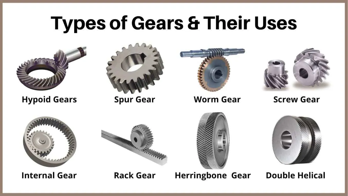
Damage Type Recognition Guide
🔴 Pitting
Small craters (0.1–3 mm diameter) on the tooth flank, typically clustered near the pitch line. Initial pitting may be self-arresting; progressive pitting expands and indicates the gear set is operating at or above rated load.
🔴 Spalling
Large flake-out areas (>3 mm) with a rough, irregular crater surface. Indicates advanced surface fatigue, often from pitting that was not arrested. Requires gear set replacement; spalling is not self-limiting.
🟣 Scuffing
Directional score marks running lengthwise along the tooth face from heel to toe. Smooth metallic streaks indicate metal-to-metal contact during oil film failure. Coarse, torn-metal appearance indicates more severe adhesive wear.
🟢 Abrasion
Overall roughening and dullness of the tooth surface, often with fine parallel scratches. Results from contamination (dirt, metal particles) in the lubricant. Address oil contamination source before replacing gears.
🔵 Fretting / Corrosion Pitting
Reddish-brown staining or rough corrosion pits on gear flanks and root fillets. Occurs when equipment sits idle with contaminated or depleted oil. Inspect carefully — corrosion pits at the root fillet are fatigue crack initiation sites.
⚫ Root Cracking
Hair-fine cracks running across the tooth root fillet, perpendicular to the tooth length. Extremely serious — imminent tooth fracture. Requires immediate shutdown. Cracks may require dye penetrant or magnetic particle testing to reveal clearly.
04
Backlash Measurement
Dial Indicator Required · Quantitative Wear Data
Backlash — the small clearance between non-driving tooth flanks when the driving flank is in contact — increases as gear tooth flanks wear away. Measuring backlash at intervals and trending the results provides a direct quantitative index of tooth wear progression. The measurement procedure requires the gearbox to be opened, the ring gear secured against rotation, and a dial indicator mounted against a pinion tooth flank at the pitch radius (approximately halfway between the tooth tip and root, at the mid-face point).
Rock the pinion shaft back and forth while reading the indicator — the total movement is the circumferential backlash. To convert to normal backlash (perpendicular to the tooth surface), multiply by sin(pressure angle) × cos(spiral angle). Compare against the original as-manufactured backlash specification. For most industrial bevel gears, backlash increase of more than 50% above the nominal value indicates significant tooth wear requiring a replacement decision. Backlash below nominal is also a concern — it may indicate reassembly errors or thermal expansion effects locking the mesh.
Alongside backlash, check shaft axial play with the indicator positioned axially at the shaft end. Excessive axial play (more than 0.1–0.2 mm in most industrial applications) indicates bearing preload loss — which itself causes backlash variability and gear contact pattern deterioration that mimics tooth wear damage in its symptoms. Distinguishing bearing preload loss from tooth wear damage is critical before deciding whether to replace the gear set or simply reset the bearing arrangement.
05
Vibration Analysis: Frequency-Domain Diagnostics
Accelerometer + Analyser Required · Non-Intrusive
Vibration analysis using an accelerometer and spectrum analyser is the most powerful non-intrusive condition monitoring technique for rotating machinery, and bevel gearboxes are particularly well-suited to this approach. The gear mesh frequency (GMF = shaft RPM/60 × tooth count) produces a characteristic peak in the vibration spectrum. In a healthy gear set, the GMF peak is present and relatively low in amplitude, with small sidebands spaced at shaft frequency intervals around it. Developing faults produce characteristic spectral signatures that allow specific fault types to be identified.
Single-tooth damage (a chip or spall on one tooth) produces amplitude modulation of the GMF, creating sidebands spaced at the shaft frequency of the damaged gear. These sidebands grow in amplitude as the damage progresses. Surface fatigue (pitting distributed across multiple teeth) produces a general rise in the noise floor around the GMF rather than discrete sidebands. Bearing defects produce characteristic sub-synchronous peaks at bearing defect frequencies (BPFO, BPFI, BSF) that differ from gear mesh frequencies and can be calculated from bearing geometry specifications.
The critical value of vibration analysis lies in trend monitoring over time rather than point-in-time measurement. Establishing a baseline spectrum at commissioning or after a major overhaul, then comparing subsequent spectra to the baseline at regular intervals, allows developing faults to be detected when amplitudes first begin to rise — often while the gear set still has weeks or months of remaining service life before failure, enabling planned replacement rather than emergency intervention.
06
Contact Pattern Inspection with Engineer’s Blue
Prussian Blue Required · Reveals Setup Errors
The contact pattern test reveals exactly where the gear tooth surfaces are making contact — information that neither vibration analysis, oil analysis, nor backlash measurement can provide directly. It distinguishes between tooth wear caused by surface fatigue (from correct but overloaded contact) and wear caused by incorrect contact geometry arising from setup errors or housing distortion. A setup-induced contact pattern error continues to cause damage at any load level and cannot be resolved by gear replacement alone — the mounting distance must also be corrected.
The procedure: apply a thin, uniform coat of engineer’s blue (Prussian blue paste or marking compound) to 4–6 consecutive ring gear teeth. Rotate the pinion through several mesh cycles under light, manually-applied load. The blue transfers from the ring gear teeth to the pinion teeth, leaving a pattern that maps the contact zone. Photograph immediately before the pattern dries and smears.
Pattern Interpretation Quick Reference
✓ CORRECT
Oval pattern, 50–65% of face width, centred between tip and root, slightly biased toward the small (toe) end. No contact within 2 mm of tooth ends.
⚠ HEEL CONTACT
Contact concentrated at large end. Pinion mounting distance too large. Move pinion inward to correct. Will cause spalling at ring gear heel end.
⚠ TOE CONTACT
Contact at small end only. Pinion too close to ring gear. Increase pinion mounting distance until pattern shifts toward centre.
✗ TIP/ROOT CONTACT
Contact at tooth tip or root only. Suggests incorrect ring gear offset or serious housing distortion. Expert assessment required.
07
Non-Destructive Testing: MPI and Dye Penetrant
Specialist Equipment · Reveals Sub-Surface Cracks
Magnetic Particle Inspection (MPI)
Magnetic particle inspection is the definitive method for detecting fatigue cracks in steel bevel gears — particularly root-fillet cracks that are the immediate precursor to tooth fracture. The gear or individual teeth are magnetised using a yoke or coil, then fine ferrous particles suspended in a carrier fluid are applied to the surface. Cracks and other discontinuities disrupt the magnetic field and attract the particles, creating visible indications that are far more revealing than visual inspection alone. MPI can detect cracks as small as 0.1 mm in length at the surface and sub-surface defects down to about 3–4 mm depth, making it the most sensitive crack detection method available for steel gears.
Dye Penetrant Testing (PT)
Dye penetrant testing is used for non-magnetic materials (stainless steel, bronze, aluminium) or as a supplementary method for surface-breaking crack detection on steel gears. A coloured or fluorescent penetrant is applied to the cleaned gear surface, allowed to dwell for 5–30 minutes to seep into any cracks or porosity, then removed from the surface while leaving penetrant trapped in discontinuities. A developer is applied to draw the trapped penetrant out, revealing crack indications as clearly visible lines. Penetrant testing is simpler and cheaper than MPI but is limited to surface-breaking defects only — it cannot reveal sub-surface cracks.
When NDT Testing Is Warranted
NDT testing of bevel gears is appropriate in high-value equipment (mining, offshore, aerospace), following any event of severe overloading or shock loading that may have initiated subsurface cracks, when visual inspection reveals suspicious surface marks that could be cracks or could be tooling marks, and as part of a post-incident root cause analysis. In Australian mining operations, NDT testing of critical gearbox components prior to returned service following a breakdown is increasingly standard practice under the requirements of state mine safety regulators.
Method Selection Matrix: Which Test for Which Situation?
Use this guide to select the appropriate inspection method for your situation. Multiple methods are often used in combination for comprehensive assessment.
| Situation |
Recommended Methods |
When to Shut Down |
| Routine preventive maintenance |
01 Sensory + 02 Oil Analysis + 04 Backlash |
Only if anomalies found |
| New noise or vibration detected |
01 Sensory + 05 Vibration Analysis |
If vibration amplitude rising |
| Oil analysis showing elevated Fe |
02 Oil (trend) + 03 Visual + 04 Backlash |
If visual confirms spalling |
| Suspected overload event |
03 Visual + 06 Contact Pattern + 07 MPI |
If cracks or severe damage found |
| Excessive backlash found |
03 Visual + 06 Contact Pattern + 04 Axial play |
Gear replacement decision |
| High-value/safety-critical equipment |
All 7 methods at major overhaul |
Per risk assessment protocol |
What Customers Found Using These Methods
★★★★★
“Method 2 — oil analysis — caught pitting on our ring gear before any noise was audible. The lab flagged rising iron two months before we found spalling on the tooth flanks during the follow-up visual inspection. Saved us a seized gearbox.”
— K. Oduya, Reliability Supervisor · Mackay, QLD
★★★★★
“The contact pattern test (Method 6) revealed our rebuilt gearbox had heel contact — a setup error by the previous repairer. We didn’t know until we used the blue method per Ever-Power’s guidance. The gears were wearing at twice the expected rate.”
— B. Lawson, Engineering Manager · Darwin, NT
★★★★☆
“We implemented routine backlash measurements across our four conveyor bevel gearboxes. In 18 months, one unit showed twice the backlash increase rate of the others. Early inspection confirmed localised tooth wear from a bearing preload problem caught well before failure.”
— L. Ferreira, Maintenance Planner · Wollongong, NSW
★★★★★
“After a high-current motor trip event, we were unsure whether the gearbox had been overstressed. Ever-Power recommended MPI testing before return to service. No cracks found — we returned the equipment with confidence rather than gambling on a high-value machine.”
— A. McGregor, Asset Manager · Broken Hill, NSW
Frequently Asked Questions: Bevel Gear Diagnostics
What noise does a failing bevel gear make?
A single damaged tooth produces a regular clicking at shaft rotation frequency. Multiple damaged teeth or progressive surface fatigue creates a continuous whining or grinding sound that intensifies with load. Bearing deterioration within the bevel gearbox produces a lower-frequency growling or rumbling that is less precisely correlated to shaft speed. Use a stethoscope on the casing to isolate the noise source location.
How do I know if my bevel gear needs replacing or just adjustment?
Key distinction: a contact pattern error (heel or toe contact) requires mounting distance adjustment, not gear replacement — the gear teeth themselves may be in good condition. Tooth surface damage (pitting, spalling, scuffing) beyond AGMA acceptance limits requires gear replacement. Excessive backlash from bearing preload loss requires bearing adjustment or replacement, not necessarily gear replacement. Perform a full assessment before ordering new gears.
How often should backlash be measured on industrial bevel gears?
For heavy-duty applications (mining, construction, heavy agriculture), annually or every 4,000 operating hours. For medium-duty industrial applications, every 2–3 years. For light-duty applications, every 5 years or at major overhauls. Always measure and record at commissioning of a new gear set to establish the baseline against which wear is compared.
Can I run a bevel gear with light pitting on the tooth flanks?
Initial or progressive pitting that is not growing may be acceptable — AGMA standards define maximum acceptable pitting areas as a percentage of the tooth contact zone. However, any pitting at or near the tooth root fillet is more serious as it can initiate root cracks. If pitting is growing between successive inspections, the gear set should be operated at reduced load if possible and a replacement obtained before catastrophic spalling or tooth fracture occurs.
What does it mean if my bevel gearbox runs hot?
Normal operating temperature for most industrial bevel gearboxes is 50–80°C casing temperature (measured on the outside of the housing). Temperatures above 90°C indicate either: oil level too low, oil viscosity too high for the operating speed, bearing preload too tight, or a contact pattern error causing concentrated surface stress and friction. Measure all potential causes before concluding it is a gear damage issue.
Is vibration analysis reliable for detecting bevel gear faults early?
Yes — trend monitoring of vibration at the gear mesh frequency and its harmonics is one of the most sensitive early-warning techniques available. A well-set-up program with baseline spectra and action thresholds can detect developing tooth faults 6–12 weeks before failure in many cases. However, bevel gear vibration signatures are slightly more complex to interpret than spur or helical gear signatures due to the conical geometry and the directionality of the tooth force vector. Specialist interpretation is recommended for critical equipment.
Do spiral bevel gears and straight bevel gears fail in the same ways?
The damage modes are the same (pitting, spalling, scuffing, abrasion, tooth fracture), but the distribution differs. Straight bevel gears are more prone to impact-related root fracture because of their sudden full-face engagement. Spiral bevel gears are more prone to pitting from Hertzian contact stress concentrated at the pitch line because their higher contact ratio loads each tooth at higher mean contact stress. Maintenance inspection priorities should reflect the gear type in each application.
What is the best way to detect a root crack before tooth fracture?
Magnetic particle inspection (MPI) is the most sensitive and reliable method for detecting root-fillet cracks in steel bevel gears. Dye penetrant testing is a lower-cost alternative for surface-breaking cracks only. Visual inspection with magnification can detect visible cracks in advanced cases but will miss early-stage fine cracks. If visual inspection reveals any mark that might be a crack, treat it as a crack and confirm with MPI before returning the equipment to service.
Can a worn bevel gear be repaired rather than replaced?
In general, no — worn bevel gear tooth profiles cannot be economically re-machined to restore the original geometry. Some very large, expensive gears (such as those in cement mill or large mining equipment) have been successfully re-toothed by specialist gear repair shops, but this is rare and highly application-specific. For most industrial bevel gear sets, replacement as a matched pair is the correct approach once wear has progressed beyond AGMA limits.
Where can I get bevel gear diagnostic support and replacement gears in Australia?
Australia Ever-Power at Condell Park NSW 2200 provides technical diagnostic support, reverse-engineered replacement gear sets, and comprehensive maintenance guidance for bevel gear applications across all Australian states. Contact our team at
[email protected] to discuss your situation and receive expert guidance on the most cost-effective path forward.
Need Bevel Gear Inspection Support or Replacement Parts?
Australia Ever-Power’s Condell Park NSW team provides diagnostic consultation, precision replacement gear sets, and rapid delivery across all Australian states and territories.
📧 [email protected]
