
Why Correct Identification Matters Before You Order
Ordering the wrong type of bevel gear is one of the most common — and costly — mistakes in gear procurement. A straight bevel gear ordered when the application requires spiral bevel will fail rapidly due to insufficient load capacity and excessive noise. A hypoid gear sent back because the customer expected a standard spiral bevel set will not mesh with the existing housing geometry. A zerol bevel gear mis-identified as a straight bevel gear will have different axial thrust characteristics that the bearing arrangement cannot accommodate.
The five principal bevel gear types — straight, spiral, hypoid, zerol, and mitre — can all be distinguished from each other through a combination of visual inspection, measurement, and functional testing. None of these identification steps requires specialist measuring equipment; the most critical checks can be performed with calipers, a straight edge, and careful observation. This guide walks through each identification method systematically, starting with the most obvious visual differences and progressing to the more subtle dimensional checks that distinguish gear types that superficially resemble each other.
Australia Ever-Power in Condell Park NSW 2200 regularly assists customers with gear identification for replacement sourcing. Our reverse engineering service can work from a physical sample, photographs, or dimensional measurements to confirm specification and manufacture a correct replacement. Contact [email protected] if you need expert identification support.
Visual Identification: First Look at the Tooth Form
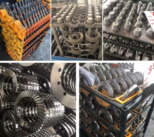
The most immediately informative identification step is direct visual examination of the tooth profile direction. Stand the gear on a flat surface with the large face (outer diameter) facing you and look straight at the tooth surfaces from the face end. The appearance of the teeth from this perspective immediately separates the five principal types:
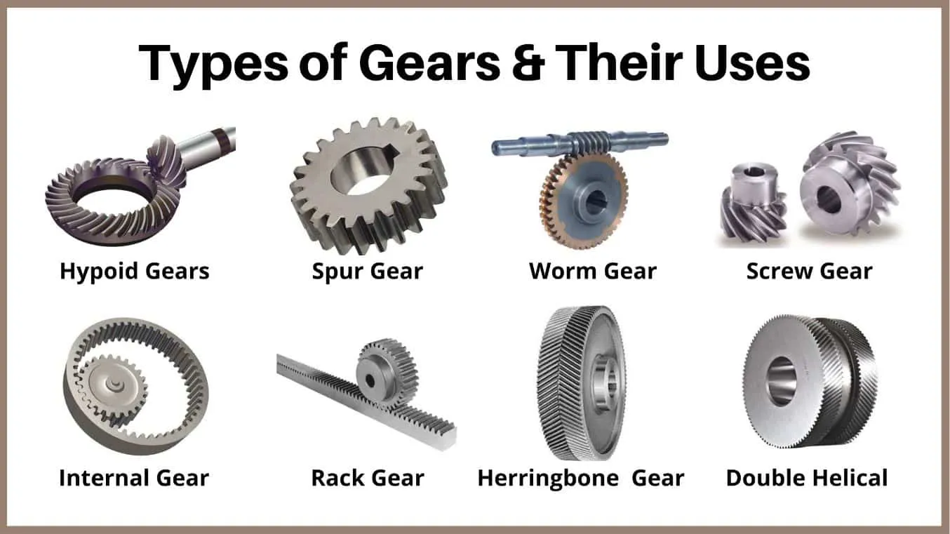
Teeth run straight from the small end to the large end of the cone, aligned with the cone element (the geometric line from tooth tip to pitch apex). Viewed from the face end, teeth appear as straight radial lines pointing toward the gear centre. No curvature is visible in any plane of view.
Teeth are curved — they start at the small end and sweep in a helical arc toward the large end at a visible angle (typically 35° to the cone element). Viewed from the face end, teeth appear as curved lines that arc either clockwise or counter-clockwise from the small end toward the tooth tip at the large end.
Like spiral bevel gears, zerol gears have curved teeth. However, the curvature is much less pronounced — at the tooth midface, the tangent to the tooth curve is parallel to the cone element (zero mean spiral angle). The teeth appear gently curved rather than sharply helical, similar to a mild banana curvature.
Visually resembles spiral bevel gears with curved, helical teeth. The key visual distinction is shaft axis offset — the pinion shaft centre does not align with the ring gear’s rotational axis. Looking at a mated hypoid pair, the pinion sits below (or above) the ring gear centreline rather than intersecting it.
A specific subset of straight bevel gears with equal tooth counts on both mating gears, giving a 1:1 speed ratio. The pitch cone angle of each gear is exactly 45°. Viewed from the face end at the tooth pitch surface, the tooth half-angle appears equal — the gear looks “symmetric.” Both gears in the pair are identical.
Step-by-Step Measurement Identification
Set the gear on a flat reference surface with the cone apex pointing down. Using a digital protractor or sine bar, measure the angle of the pitch cone surface relative to the gear axis. A mitre gear will show exactly 45°. A gear in a high-ratio pair will show a small pinion cone angle (under 20°) or a large ring gear cone angle (over 70°). This measurement identifies whether the gear is a mitre and gives the gear ratio when compared with the mating gear.
Count all teeth on both the pinion and ring gear. Calculate u = z₂/z₁. If u = 1 and both gears have 45° cone angles, you have a mitre gear set. If u is a whole number or simple fraction, the gear set is a standard ratio. Note that hypoid pinions have more teeth relative to ring gear than equivalent spiral bevel sets at the same ratio — a hypoid pinion typically has 10–15% more teeth than a spiral bevel pinion for the same ratio and ring gear diameter.
With the gear set assembled in its housing or fixture, check whether the pinion shaft centreline intersects the ring gear’s rotational axis. For spiral bevel gears, both shaft axes meet at a common apex point. For hypoid gears, the pinion shaft is offset below (or above) the ring gear centreline by a defined distance — the hypoid offset. Even a small offset (as little as 10–15 mm) identifies the set as hypoid. Extend the shaft centrelines as straight lines: if they do not intersect in 3D space, it is hypoid.
Using a depth micrometer, measure the total tooth depth at the large (outer) end and the small (inner) end of the same tooth. For standard taper (ISO uniform depth) gears, the whole depth is constant across the face — both measurements should match. For duplex taper (Gleason system) gears, the tooth depth varies from outer to inner end. This distinction helps identify whether the gear was manufactured to ISO or Gleason standards, which matters for selecting a compatible replacement manufacturing process.
If the gear is being removed from service rather than newly identified, the lubricant type provides a useful corroborating clue to gear type. Hypoid gears require specifically formulated hypoid gear oil with enhanced EP additives. Standard spiral bevel gears use GL-4 or GL-5 oil but do not require the hypoid-specific formulation. If the original operator used standard gear oil in what appears to be a spiral bevel application, but the gear shows rapid tooth surface wear concentrated at the contact zone centre, it may actually be a hypoid set that was incorrectly lubricated.
Quick Identification Reference Table
Use this table for rapid field identification of bevel gear type from visual and physical inspection.
| Gear Type | Tooth Form | Cone Angle δ₁ | Shaft Axes | Ratio | Lubricant |
|---|---|---|---|---|---|
| Straight Bevel | Straight radial | Any | Intersecting | Any | GL-4 |
| Spiral Bevel | Curved, helical sweep | Any | Intersecting | Any | GL-4 / GL-5 |
| Zerol Bevel | Gently curved | Any | Intersecting | Any | GL-4 |
| Hypoid | Curved, helical sweep | Any | OFFSET | Any | Hypoid GL-5 only |
| Mitre Gear | Straight radial | 45° exactly | Intersecting | 1:1 exactly | GL-4 |
Distinguishing Spiral from Zerol: The Spiral Angle Test
Spiral and zerol bevel gears both have curved teeth, making them the most easily confused pair. The definitive distinction is the mean spiral angle ψm, measured at the tooth midface. For a standard spiral bevel gear, ψm = 35° (or other non-zero values between 25° and 45°). For a zerol bevel gear, ψm = 0° at the midface — the tooth curves, but the tangent to the tooth at the midpoint of the face width runs parallel to the cone element.
To perform this test without sophisticated equipment: lay a thin straight edge along the tooth midface (halfway between the large and small ends of the tooth). For a spiral bevel gear, the straight edge will sit at a clearly visible angle to the cone element direction. For a zerol bevel gear, the straight edge at the midface will align approximately parallel to the cone element — confirming the zero mean spiral angle. Near the tooth ends, the zerol tooth will still show curvature (since the tooth form is curved), but the midface tangent direction is the distinguishing measurement.
The practical significance of correctly distinguishing these two types: zerol bevel gears produce minimal axial thrust at the bearings (because the zero spiral angle means the helical force component cancels), while spiral bevel gears produce substantial axial thrust that must be accommodated by appropriate tapered roller or angular contact bearings. Installing a replacement spiral bevel gear set in a housing that was designed for zerol bevel gears — without understanding this distinction — will overload the bearings in the axial direction and cause premature bearing failure that appears unrelated to the gear itself.
Measuring Module and Checking for Metric vs Imperial
Once the gear type is confirmed, the next critical identification step is determining the module (or diametral pitch for inch-system gears). For a bevel gear, measure the outer diameter at the large (outer) tooth tip circle. Count the number of teeth. The outer module me ≈ (outer tip diameter) / (tooth count + 2·cos δ × addendum coefficient). In practice, since the addendum coefficient is usually 1.0 for standard gears, outer module ≈ (outer pitch diameter) / (tooth count).
To find the outer pitch diameter: measure the outer tip diameter with calipers, then subtract twice the tooth tip height (approximately 2 × outer module) from the tip diameter to get the pitch diameter. For a rough check: module = pitch diameter / tooth count. If the result is close to a standard ISO preferred module value (1, 1.25, 1.5, 2, 2.5, 3, 4, 5, 6, 8, 10…), the gear is metric. If the result is close to 25.4 / N where N is a whole number (e.g., 25.4/6 = 4.233, corresponding to 6 DP), the gear is inch system with diametral pitch N.
This metric vs inch distinction is critical for replacement sourcing. A 6 DP gear has a module of approximately 4.233 — close to module 4, but not identical. Running a module 4 gear against a 6 DP gear will appear to mesh at the correct ratio but will have incorrect tooth proportions, wrong backlash, and potentially interference at the tooth ends, causing rapid failure. Always confirm metric or inch system before specifying replacements. Australia Ever-Power can manufacture in either system; just specify clearly which is required.
Replacement Cost by Bevel Gear Type (AUD Reference)
Indicative pricing for replacement bevel gear sets, Module 4, single pair. Correct identification saves the cost of ordering the wrong type.
| Type | Price / Pair (AUD) | Lead Time | Note |
|---|---|---|---|
| Straight Bevel / Mitre | $180–$420 | 2–3 weeks | Interchangeable — no matched pair |
| Zerol Bevel | $450–$900 | 3–4 weeks | Interchangeable; confirm zero spiral angle |
| Spiral Bevel (lapped) | $700–$1,400 | 3–5 weeks | Replace as matched pair; confirm hand |
| Hypoid (with documentation) | $900–$2,200 | 4–6 weeks | Requires hypoid oil; confirm offset dimension |
Customer Identification Experiences
“We sent photos of our gear to Ever-Power and they correctly identified it as a zerol bevel — not straight bevel as we assumed. The previous replacement supplier sent straight bevel gears that caused bearing failures. Correct identification saved us from repeating the same mistake.”
“Used the shaft axis check from this guide to confirm our gearbox had hypoid gears, not spiral bevel. We had been using the wrong oil for two years. Switched to proper hypoid GL-5 — the gear noise dropped noticeably within a week.”
“Needed to replace bevel gears on legacy equipment with no drawings. Ever-Power’s reverse engineering service identified the full specification from our sample gear and manufactured a matching set. Clear, reliable process.”
“The tooth depth variation test helped us identify a Gleason duplex-taper ring gear from a ISO uniform-depth unit — details that would have caused a major mismatch if we’d ordered the wrong manufacturing system.”
Frequently Asked Questions: Identifying Bevel Gear Types
Need Expert Bevel Gear Identification?
Australia Ever-Power · Condell Park NSW 2200 · Send your samples or photos — our engineering team will identify the specification and manufacture the correct replacement.