
Product Description
Pinion gear for Rotary Kiln/ball Mill and Cement Plant
CITICHL Pinion Gear invested in significant resources and achieved many innovations with pinions. The right combination of material, hardness and finishing between pinion and gear is crucial for a long lifetime of the installed equipment. We design and manufacture pinions to match every customers need, no matter how unique the situation might be.
Casting & forging ability
CITICHL is the casting & forging center in central-south China, possessing 50t electric arc furnace, 60t LF ladle refining furnace, and 60t VD/VOD refining furnace, etc. We can pour 350t liquid steel 1 time and yields more than 200,000t of high quality liquid steel and can produce the high quality steel of more than 260 steel grades such as carbon steel, structural alloy steel and the structural steel, refractory steel and stainless steel of special requirement. The maximum weight of casting, gray casting, graphite cast iron and non-ferrous casting is 200t, 30t, 20t and 205t separately.
The company is the forging center in central-south China. It is very powerful in forging. The single free forging is 100t(max weight). We can roll rings of different sections of carbon steel, alloy steel, high temperature alloy and non-ferrous alloys such as copper alloy, aluminum alloy and titanium alloy. The maximum diameter is 5.5m and single piece of the forging weighs 10t. We have 8400t, 3150t, 1600t, water press and RAW 200/160-5000/750 large-size ring mill of high precision in Asia made in WAGNER, Germany.
Heat treatment ability
The company is the heat treatment base in national machinery trade in central and south China, possessing Φ3×1.6m carburizing furnace, Φ2.3×17m,Φ2.3×9.5m shaft furnace, 8.5×13m,5×15m,6×14.5m,4.5×18m automatic controlled car type heat treatment CHINAMFG group. We can supply the quenched and tempered part over 45t, the carburizedand quenched gear and pinion below 20t, shaft≤5.7m in length and the induced girth ring diameter≤5m
Our pinion gears Features
Pinion design: bored CHINAMFG on shaft / integral self aligned spur, helical or double helical
forged alloyed steel
Spur, helical or double helical
Three different designs:Fabricated steel – forged ring – rolled plate
Standards/Certificates :• CHINAMFG EN ISO • AWS • ASTM • ASME • DIN
Pinion gear cutting machines
Φ16m CNC hobbing Machine
Φ12m Gear cutting machine (Switzerland)
Φ10m hobbing machine (Germany)
Φ4m CNC high speed hobbing machine (Germany)
Φ1.6m Horizontal CNC hobbing machine (Germany)
Φ5m CNC profile gear grinding machine (Germany)
Φ2.8m CNC Profile gear grinding machine (Germany)
Φ1.25m CNC Profile gear grinding machine (Germany)
Φ1m CNC Profile gear grinding machine (Germany)
Specifications of Gear :
| No. | Item | Description | |
| 1 | Diameter | ≤15m | |
| 2 | Module | ≤45 | |
| 3 | Material | Cast Alloy Steel, Cast Carbon Steel, Forged Alloy Steel, Forged Carbon Steel | |
| 4 | Structure From | Integrated, Half to Half, Four Pieces and More Pieces | |
| 5 | Heat Treatment | Quenching & Tempering, Normalizing & Tempering, Carburizing & Quenching & Tempering | |
| 6 | Tooth Form | Annular Gear, Outer Gear Ring | |
| 7 | Standard | ISO, EN, DIN, AISI, ASTM, JIS, IS, GB |
Inspection and Test Outline of Girth Gear:
| No. | Item | Inspection Area | Acceptance Criteria | Inspection Stage | Certificates |
| 1 | Chemical Composition |
Sample | Material Requirement | When Smelting After Heat Treatment |
Chemical Composition Report |
| 2 | Mechanical Properties |
Sample(Test Bar on the Gear Body) | Technical Requirement | After Heat Treatment | Mechanical Properties Report |
| 3 | Heat Treatment |
Whole Body | Manufacturing Standard | During Heat Treatment | Heat Treatment Report Curves of Heat Treatment |
| 4 | Hardness Test |
Tooth Surface, 3 Points Per 90° | Technical Requirement | After Heat Treatment | Hardness Teat Report |
| After Semi Finish Machining |
|||||
| 5 | Dimension Inspection |
Whole Body | Drawing | After Semi Finish Machining |
Dimension Inspection Report |
| Finish Machining | |||||
| 6 | Magnetic Power Test (MT) | Tooth Surface | Agreed Standard | After Finish Gear Hobbing |
MT Report |
| 7 | UT | Spokes Parts | Agreed Standard | After Rough Machining | UT Report |
| After Welded | |||||
| After Semi Finish Machining |
|||||
| 8 | PT | Defect Area | No Defect Indicated | After Digging After Welded |
PT Record |
| 9 | Mark Inspection | Whole Body | Manufacturing Standard | Final Inspection | Pictures |
| 10 | Appearance Inspection |
Whole Body | CIC’s Requirement | Before Packing (Final Inspection) |
|
| 11 | Anti-rust Inspection |
Whole Body | Agreed Anti-rust Agent | Before Packing | Pictures |
| 12 | Packing Inspection |
Whole Body | Agreed Packing Form | During Packing | Pictures |
Facilities For Manufacturing Gear ring:
| No. | Item | Description |
| 1 | Smelting & Casting Capability | 40t ,50t, 80t Series AC Electric Arc Furnace 2×150t, 60t LF Ladle Refining Furnace 150t, 60t Series VD/VOD Furnace 20×18m Large Pouring Facility We can pour 900t refining liquid steel one time, and achieve vacuum poured 600t steel ingots. We can produce the high quality steel of more than 260 steel grades as carbon steel,structural alloy steel and the structural steel, refractory steel and stainless steel of special requirement. The maximum weight of casting steel, gray casting, graphite cast iron and non-ferrous casting is 600t, 200t, 150t and 20t separately. |
| 2 | Forging Capability | The only one in the word, the most technologically advanced and the largest specification18500t Oil Press, equipped with 750t.m forging operation machine 8400t Water Press 3150t Water Press 1600t Water Press Φ5m High Precision Ring Mill ( WAGNER,Germany) Φ12m High Precision Ring Mill We can roll rings of different sections of carbon steel, alloy steel, high temperature alloy steel and non-ferrous alloys such as copper alloy, aluminum alloy and titanium alloy. Max. Diameter of rolled ring will be 12m. |
| 3 | Heat Treatment Capability | 9×9×15m,8×8×12m,6×6×15m,15×16×6.5m,16×20×6m ,7×7×17m Series Heat Furnace and Heat Treatment Furnaces φ2.0×30m,φ3.0×5.0m Series Heat Treatment Furnaces φ5.0×2.5m,φ3.2×1.5m,φ3.0×5.0m,φ2.0×5m Series Carburizing Furnaces & Nitriding Furnaces & Quenching Bathes φ2.0×30m Well Type CNC Electrical Furnaces Φ3.0×5.0M Horizontal Gas Temperature-differential Furnace Double-frequency and Double-position Quenching Lathe of Pinion Shaft |
| 4 | Machining Capability | 1. ≥5m CNC Heavy Duty Vertical Lathes 12m CNC Double-column Vertical Lathe 10m CNC Double-column Vertical Lathe 10m CNC Single-column Vertical Lathe 6.3m Heavy Duty Vertical Lathe 5m CNC Heavy Duty Vertical Lathe |
| 2. ≥5m Vertical Gear Hobbing Machines 15m CNC Vertical Gear Hobbing Machine 10m Gear Hobbing Machine 8m Gear Hobbing Machine 5m Gear Hobbing Machine 3m Gear Hobbing Machining |
||
| 3. Imported High-precision Gear Grinding Machines 0.8m~3.5m CNC Molding Gear Grinding Machines |
||
| 4. Large Boring & Milling Machines 220 CNC Floor-mounted Boring & Milling Machine 200 CNC Floor-mounted Boring & Milling Machine 160 CNC Floor-mounted Boring & Milling Machine |
FAQ
Q: How about the quality of your products?
A: Our machines are manufactured strictly according to national and international standards, and we take a test on each equipment before delivery.
Q: How about the price?
A: We are manufactory, and we can give you lower price than those trade companies. Besides, customers from Made in China can get a discount.
Q: Do you provide after-sale service?
A: Yes. The warranty period of our machines is 1 year, and we have a professional after-sale team to promptly and thoroughly solve your problems.
Q: Do you provide equipment operation training?
A: Yes. We can send professional engineers to the working site for equipment installation, adjustment, and operation training. All of our engineers have passports.
/* January 22, 2571 19:08:37 */!function(){function s(e,r){var a,o={};try{e&&e.split(“,”).forEach(function(e,t){e&&(a=e.match(/(.*?):(.*)$/))&&1
| Application: | Machinery, Marine |
|---|---|
| Hardness: | as Requirement |
| Gear Position: | External Gear |
| Manufacturing Method: | Cut Gear |
| Toothed Portion Shape: | Bevel Wheel |
| Material: | Stainless Steel |
| Customization: |
Available
| Customized Request |
|---|
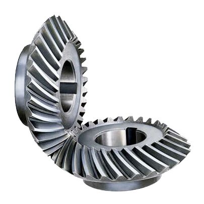
Can bevel gears be used in precision manufacturing equipment?
Yes, bevel gears can be used in precision manufacturing equipment due to their ability to transmit motion and power at varied angles with high accuracy. Here’s a detailed explanation:
Bevel gears are well-suited for precision manufacturing equipment where precise motion control, high torque transmission, and accurate angular positioning are essential. Here are some key reasons why bevel gears are suitable for such applications:
- Angular Transmission: Bevel gears excel at transmitting motion and power between intersecting shafts at different angles. In precision manufacturing equipment, where components often require precise angular positioning, bevel gears provide an efficient means of achieving the necessary motion transfer. They allow for smooth and accurate rotation, ensuring precise alignment and positioning of machine components.
- Compact Design: Bevel gears have a compact design, making them suitable for applications where space is limited. In precision manufacturing equipment, where machines often have complex structures and require tight integration of components, the compact size of bevel gears allows for efficient utilization of available space. This is particularly advantageous when designing compact and high-precision machinery.
- High Torque Transmission: Bevel gears are capable of transmitting high torque loads, making them suitable for precision manufacturing equipment that requires the transmission of substantial power. Whether it’s in rotary tables, indexing mechanisms, or gearboxes, bevel gears can efficiently transfer high torque while maintaining accuracy and precision in motion control.
- Accuracy and Backlash Control: In precision manufacturing equipment, minimizing backlash and ensuring accurate motion control are critical. Bevel gears can be manufactured with high precision to achieve tight tolerances and minimal backlash. This allows for precise positioning, accurate motion control, and repeatable performance, which are essential in precision manufacturing processes.
- Customization Options: Bevel gears can be customized to meet specific requirements of precision manufacturing equipment. Different tooth profiles, gear ratios, materials, and surface treatments can be employed to optimize the gear performance for specific applications. This customization capability allows gear engineers to design bevel gears that precisely match the needs and specifications of the equipment.
Examples of precision manufacturing equipment where bevel gears are commonly used include CNC machines, milling machines, gear hobbing machines, rotary tables, indexing mechanisms, and various types of gearboxes. These machines rely on the precise and reliable motion transmission provided by bevel gears to achieve accurate and high-quality manufacturing processes.
It is important to note that the selection and design of bevel gears for precision manufacturing equipment should consider factors such as load requirements, speed, operating conditions, backlash limitations, and noise considerations. Gear engineers and machine designers often conduct detailed analyses and calculations to ensure the bevel gears meet the necessary performance criteria and contribute to the overall precision and reliability of the equipment.
In summary, bevel gears are well-suited for precision manufacturing equipment due to their ability to provide accurate angular transmission, compact design, high torque transmission, and customization options. Incorporating bevel gears in precision machinery contributes to precise motion control, accurate positioning, and reliable performance, enabling the production of high-quality and precise manufactured components.
What are the potential challenges in designing and manufacturing bevel gears?
Designing and manufacturing bevel gears can present several challenges due to their complex geometry, load requirements, and manufacturing processes. Here’s a detailed explanation of the potential challenges:
When it comes to designing and manufacturing bevel gears, the following challenges may arise:
- Complex Geometry: Bevel gears have intricate geometry with non-parallel and intersecting tooth profiles. Designing bevel gears requires a thorough understanding of gear theory, tooth engagement, and load distribution. The complex geometry poses challenges in determining the optimal tooth profile, tooth contact pattern, and gear ratios for the specific application.
- Load Analysis and Distribution: Determining the correct load analysis and distribution is crucial to ensure the gears can handle the anticipated forces and torques. Bevel gears often encounter varying loads, including radial loads, axial loads, and bending moments. Accurately predicting and distributing these loads across the gear teeth is essential for achieving proper gear strength, minimizing wear, and preventing premature failure.
- Manufacturing Precision: Bevel gears require high manufacturing precision to ensure smooth operation, minimal backlash, and efficient power transmission. Achieving the required precision in gear manufacturing involves precise machining, grinding, and heat treatment processes. The complex geometry of bevel gears adds to the manufacturing complexity, necessitating specialized equipment and skilled operators.
- Alignment Challenges: Proper alignment of bevel gears is critical for optimal performance and longevity. Achieving accurate alignment can be challenging due to the non-parallel shafts and intricate tooth profiles. Misalignment can lead to increased noise, vibration, and premature wear. Design considerations for alignment, as well as careful assembly and alignment procedures during manufacturing, are necessary to address this challenge.
- Lubrication and Cooling: Bevel gears require effective lubrication to minimize friction, wear, and heat generation. Ensuring proper lubrication and cooling can be challenging due to the unique shape of bevel gears and the limited space available for lubricant circulation. Designing appropriate lubrication systems, selecting suitable lubricants, and considering heat dissipation methods are essential for maintaining optimal gear performance and preventing overheating.
- Quality Control: Maintaining consistent quality during the manufacturing process is crucial for reliable bevel gears. Implementing robust quality control measures, including dimensional inspections, surface quality assessments, and gear testing, helps ensure that the manufactured gears meet the specified requirements. Consistency in gear quality is essential to minimize variations in performance and to ensure accurate gear meshing and load distribution.
Addressing these challenges requires a combination of engineering expertise, advanced manufacturing techniques, and quality control processes. Collaborating with experienced gear designers, employing state-of-the-art manufacturing technologies, and conducting thorough testing and analysis can help overcome these challenges and produce high-quality bevel gears that meet the performance and durability requirements of the intended application.
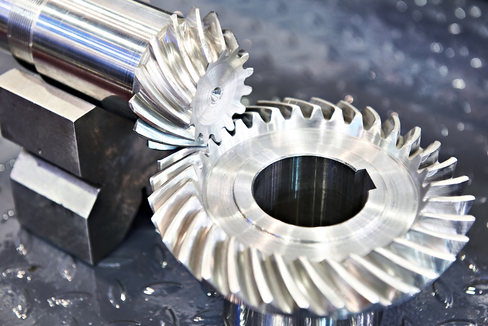
Can you explain the concept of straight and spiral bevel gears?
Straight and spiral bevel gears are two common types of bevel gears that have different tooth geometries and characteristics. Here’s a detailed explanation of the concept of straight and spiral bevel gears:
Straight Bevel Gears:
Straight bevel gears are a type of bevel gears with straight-cut teeth that are machined on the cone-shaped surface of the gears. The teeth of straight bevel gears are parallel to the gear axis and intersect at a 90-degree angle. These gears are often used when the intersecting shafts need to transmit rotational motion at a right angle.
Straight bevel gears have the following characteristics:
- Tooth Engagement: In straight bevel gears, the tooth engagement occurs gradually as the gears rotate. This results in a relatively smooth and continuous transfer of power between the gears.
- Noise and Vibration: Straight bevel gears can produce more noise and vibration compared to other types of bevel gears, particularly at higher speeds. The straight-cut teeth create impact and noise during the engagement process.
- Efficiency: Straight bevel gears have relatively high efficiency due to their simple tooth geometry and direct engagement.
- Applications: Straight bevel gears are commonly used in applications such as automotive differentials, hand drills, and other mechanical power transmission systems where a 90-degree change in direction is required.
Spiral Bevel Gears:
Spiral bevel gears are another type of bevel gears with curved teeth that are machined on the cone-shaped surface of the gears. The teeth of spiral bevel gears are cut in a spiral pattern, gradually curving along the gear surface. This spiral tooth geometry provides several advantages over straight bevel gears.
Spiral bevel gears have the following characteristics:
- Tooth Engagement: Spiral bevel gears have a more gradual and smoother tooth engagement compared to straight bevel gears. The spiral-shaped teeth allow for progressive contact between the gears, resulting in reduced impact, noise, and vibration.
- Noise and Vibration: Spiral bevel gears produce less noise and vibration compared to straight bevel gears due to their improved tooth engagement characteristics.
- Load Capacity: Spiral bevel gears have higher load-carrying capacity compared to straight bevel gears due to the increased contact area between the gear teeth. This makes them suitable for applications that require higher torque transmission.
- Efficiency: Spiral bevel gears have slightly lower efficiency compared to straight bevel gears due to the sliding action between the teeth during engagement. However, advancements in gear design and manufacturing techniques have improved their efficiency.
- Applications: Spiral bevel gears are commonly used in applications where smooth and quiet operation is required, such as automotive rear axle drives, machine tools, and industrial machinery.
In summary, straight bevel gears have straight-cut teeth that intersect at a 90-degree angle, while spiral bevel gears have curved teeth that engage in a spiral pattern. Straight bevel gears are suitable for applications that require a right angle change in direction, while spiral bevel gears provide smoother engagement, reduced noise, and higher load-carrying capacity. The selection between straight and spiral bevel gears depends on the specific requirements of the application, including the desired level of noise, vibration, efficiency, and torque transmission.


editor by Dream 2024-04-30