
Product Description
1. Part Name:
High Precision OEM Custom Transmission Parts Stainless Steel Bevel Helical Gear for Industrial Usage
2. Parts Parameter
| Process Technology | Workable size | Tolerance |
| CNC Turning | Φ0.5 – φ300 * 750 mm | +/-0.003 mm |
| CNC Milling | 510 * 1571 * 500 mm(max) | +/-0.01 mm |
| Drawing Format | IGS, STP, X_T, DXF, DWG, PRO/E, PDF | |
| Test Equipment | Projector, CMM, Altimeter, Micrometer, Thread Gages, Calipers, Pin Gauge etc. | |
3. Material Available:
| Stainless Steel | SS201, SS301, SS303, SS304, SS316, SS416 etc. |
| Steel | Mild steel, Carbon steel, 4140, 4340, Q235, Q345B, 20#, 45# etc. |
| Brass | HPb63, HPb62, HPb61, HPb59, H59, H62, H68, H80 etc. |
| Copper | C11000, C12000, C12000 C36000 etc. |
| Aluminum | AL6061, Al6063, AL6082, AL7075, AL5052, A380 etc. |
| Iron | A36, 45#, 1213, 12L14, 1215 etc. |
| Plastic | ABS, PC, PE, POM, Delrin, Nylon, PP, PEI, Peek etc. |
3.Surface Treatment Available
| Zinc plating, Chrome plating, Nickel plating, Tin plating, Polishing, Anodizing, Power-coating, Oxide black, Sandblast Anodizing, Electroless nickel, Fe/Zn8/C PER ISO 2081, etc. |
4.Our Main Production & Inspection Equipments:
MARCHTON has 3, 4, and 5 axis CNC machining centers , CNC lathes, precision CNC milling machine, grinding machine, wire cutting, EDM machine, spectrometer, electronic altimeter, CMM etc. More than 50 sets of machine and testing equipment
5. Our Advantages:
1. 10 years more experienced engineers team and well trained sales team to support every project
2. Long term cooperation is our target, quality and price are our basic to achieve it.
3. Provide different shipping way quotes to customer, accordingly customer accepted delivery time to find cheapest shipping way.
4. Well organized and clean workshop environment for all employees
6. Package & Shipping:
1. Well packed wooden box for the best protection during transportation from our door to the customer’s door
2. Small MOQ orders, we protect your parts in transportation as Soft paper\cardboard\bubble bag etc + Harden cartons + Foam
7. Application:
8. FAQ:
1) Are you a factory or a trade company?
We are manufacture, so we can offer you the competitive price and fast lead time. Welcome to visit out factory.
2) Can you provide some samples?
Yes. Samples can be provided. You just need to bear some sample cost and we’ll return it back when proceed into mass production.
3) Will my drawing be safe after you get it?
Yes. We will not release your design to the third party without your permission.
4) How to deal with the parts received when they are found to be in poor quality?
Please rest assured that all our products are QC 100% inspected and accepted with inspection report before delivery and generally there will no non-conformance; in case of non-conformance, please contact us immediately, take some pictures, we will check the problems and have them reworked or repaired at the first time. The resulting transportation costs are borne by our company.
9. Why Choose Us:
1. Quick quotation according to technical drawing
2. Professional in developing ,manufacturing & stamping
3. Provide the sample for your reference
4. High quality with competitive price
5. Work safety control and precision testing
| Application: | Fastener, Auto and Motorcycle Accessory, Hardware Tool, Machinery Accessory |
|---|---|
| Standard: | GB, EN, China GB Code, JIS Code, TEMA, ASME |
| Surface Treatment: | Brushed |
| Production Type: | Mass Production |
| Machining Method: | CNC Machining |
| Material: | Nylon, Steel, Plastic, Brass, Alloy, Copper, Aluminum, Iron |
| Samples: |
US$ 0.37/Piece
1 Piece(Min.Order) | |
|---|
| Customization: |
Available
| Customized Request |
|---|
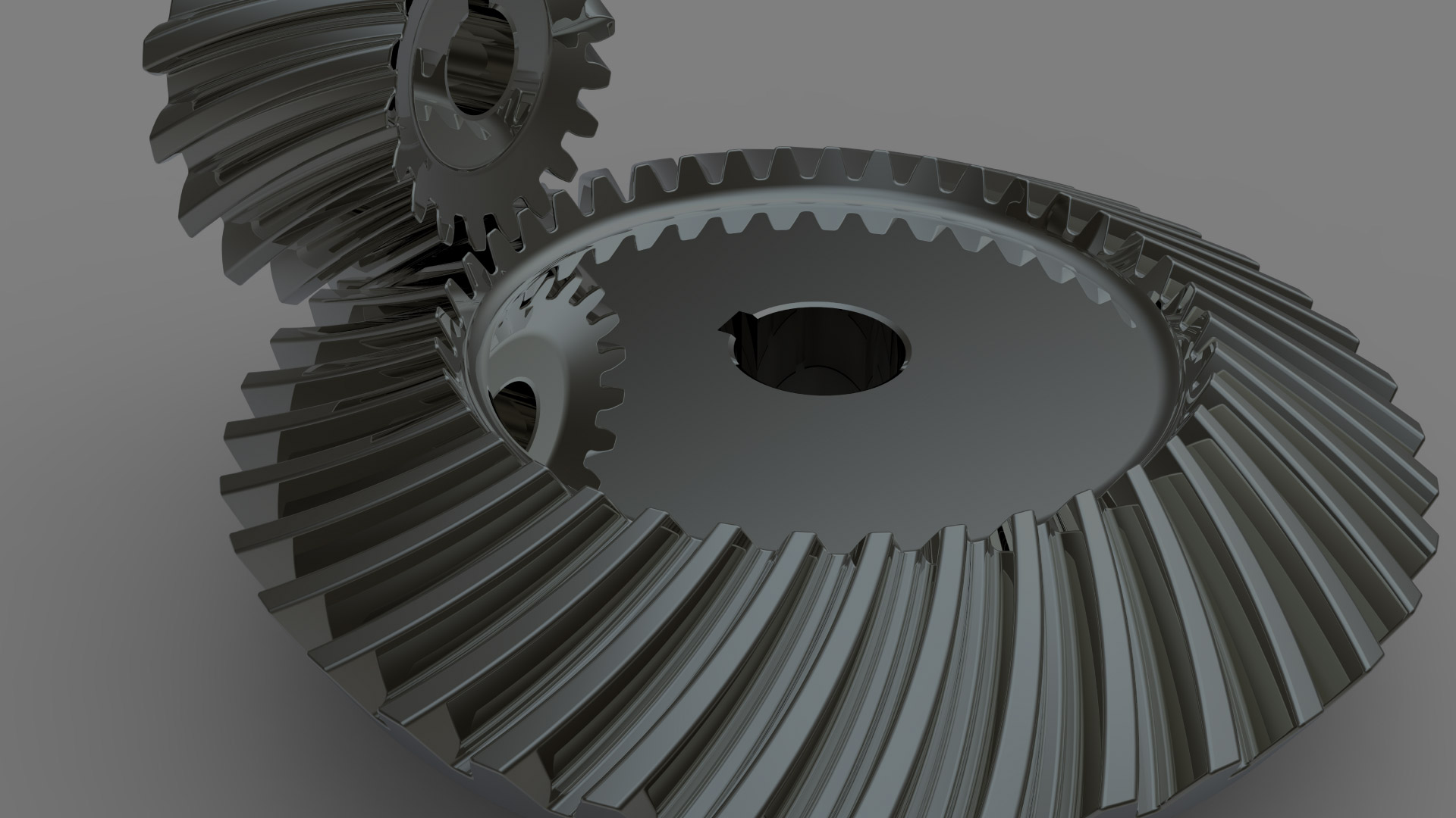
What are the advantages and disadvantages of using a bevel gear?
Bevel gears offer several advantages and disadvantages when used in mechanical systems. Understanding these pros and cons is crucial for selecting the appropriate gear type for a given application. Here’s a detailed explanation of the advantages and disadvantages of using a bevel gear:
Advantages of Bevel Gears:
- Power Transmission at Different Angles: Bevel gears are specifically designed to transmit power between intersecting shafts at different angles. They allow for efficient torque transmission and direction changes in applications where the input and output shafts are not parallel. This flexibility makes bevel gears suitable for a wide range of mechanical systems.
- Compact Design: Bevel gears have a compact and space-efficient design, allowing them to be used in applications with limited space constraints. Their ability to transmit power at an angle helps in optimizing the layout and arrangement of components in machinery and equipment.
- High Efficiency: Well-designed and properly maintained bevel gears can achieve high power transmission efficiency, typically above 95%. The efficient tooth engagement and load distribution in bevel gears minimize power losses due to friction and mechanical inefficiencies, resulting in energy-efficient operation.
- Smooth and Quiet Operation: Bevel gears generally provide smooth and quiet operation in properly designed and well-maintained systems. The meshing of the gear teeth is designed to minimize noise and vibration, ensuring smooth power transmission and reducing the need for additional noise-reducing measures.
- Versatility: Bevel gears are available in various configurations, including straight bevel, spiral bevel, and hypoid bevel gears. This versatility allows them to be used in a wide range of applications across different industries, accommodating different load capacities, speed requirements, and operating conditions.
- High Load Capacity: Bevel gears are capable of handling high loads and transmitting substantial amounts of torque. Their robust design, accurate tooth engagement, and strong materials make them suitable for heavy-duty applications where reliable power transmission is required.
Disadvantages of Bevel Gears:
- Complex Manufacturing: Bevel gears are more complex to manufacture compared to other gear types due to their three-dimensional shape and intricate tooth profiles. The manufacturing process involves specialized equipment and expertise, which can increase production costs.
- Cost: Bevel gears, especially those with high precision and load capacities, can be relatively expensive compared to other types of gears. The cost of materials, manufacturing complexity, and quality requirements contribute to their higher price.
- Potential for Noise and Vibration: In certain operating conditions, such as high speeds or misaligned gears, bevel gears can generate noise and vibration. This can be mitigated through proper design, accurate manufacturing, and maintenance practices, but additional measures may be necessary to reduce noise and vibration levels in some applications.
- Sensitive to Misalignment: Bevel gears are sensitive to misalignment, which can lead to increased friction, accelerated wear, and reduced efficiency. Proper alignment and control of backlash are essential for optimal performance and longevity of the gear system.
- Complex Lubrication: The lubrication of bevel gears can be more challenging compared to parallel-axis gears. Due to their angled tooth engagement, ensuring proper lubrication film thickness and distribution across the gear teeth requires careful consideration. Inadequate or improper lubrication can result in increased friction, wear, and reduced efficiency.
It’s important to consider these advantages and disadvantages of bevel gears in the context of specific applications and operating conditions. Proper design, selection, manufacturing, and maintenance practices can help maximize the benefits of bevel gears while mitigating their limitations.
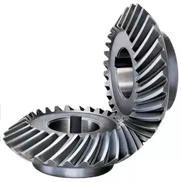
Can bevel gears be used in automotive applications?
Yes, bevel gears can be used in automotive applications due to their unique characteristics and ability to transmit power between intersecting shafts at different angles. Here’s a detailed explanation:
Bevel gears are commonly found in various automotive systems and components, offering several advantages for specific applications. Here are some key automotive applications where bevel gears are utilized:
- Differential: One of the primary applications of bevel gears in automotive systems is in the differential mechanism. The differential is responsible for distributing torque between the drive wheels while allowing them to rotate at different speeds, especially during cornering. Bevel gears, specifically hypoid gears, are used in the differential to transfer power from the driveshaft to the wheel axles at right angles. The compact size and high torque transmission capability of bevel gears make them suitable for this critical drivetrain component.
- Power Transfer: Bevel gears are utilized in automotive power transfer systems, such as transfer cases and drivelines. Transfer cases, commonly found in four-wheel drive (4WD) and all-wheel drive (AWD) vehicles, transfer power from the transmission to the front and rear axles. Bevel gears enable the necessary change in direction and torque transmission between the input and output shafts of the transfer case. Similarly, bevel gears can be used in drivelines to transfer power between differentials or between the transmission and the axles.
- Steering Systems: Bevel gears play a role in automotive steering systems, particularly in rack-and-pinion steering mechanisms. In these systems, bevel gears are used to convert the rotational motion of the steering wheel into the linear motion required for steering. Bevel gears help change the direction of motion, enabling the driver to control the vehicle’s steering angle. The compact size and precise motion transmission characteristics of bevel gears make them suitable for these steering applications.
- Auxiliary Systems: Bevel gears find application in various auxiliary automotive systems. For example, they can be used in engine timing systems to drive camshafts and synchronize valve operation. Bevel gears can also be employed in automotive differentials with limited-slip or locking capabilities, enhancing traction and vehicle stability in challenging road conditions. Additionally, they can be found in power seat adjusters, sunroof mechanisms, and other vehicle systems where torque transmission at different angles is required.
Bevel gears used in automotive applications are typically designed to withstand high loads, operate with minimal noise and vibration, and provide reliable power transmission. They are often manufactured from durable materials, such as alloy steels, and undergo heat treatment processes to enhance their strength and wear resistance.
It is important to note that the specific design and selection of bevel gears for automotive applications depend on factors such as torque requirements, space limitations, operating conditions, and cost considerations. Gear engineers and automotive manufacturers carefully consider these factors to ensure optimal performance, efficiency, and reliability in automotive systems.
In summary, bevel gears are extensively used in automotive applications, including differentials, power transfer systems, steering mechanisms, and auxiliary systems. Their ability to transmit power at varying angles, compact size, and robust construction make them well-suited for the demanding requirements of the automotive industry.
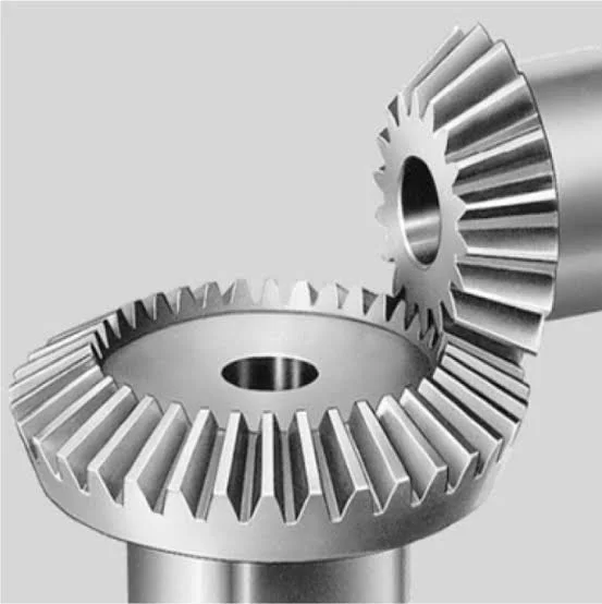
How do you calculate the gear ratio of a bevel gear?
Calculating the gear ratio of a bevel gear involves determining the ratio between the number of teeth on the driving gear (pinion) and the driven gear (crown gear). Here’s a detailed explanation of how to calculate the gear ratio of a bevel gear:
The gear ratio is determined by the relationship between the number of teeth on the pinion and the crown gear. The gear ratio is defined as the ratio of the number of teeth on the driven gear (crown gear) to the number of teeth on the driving gear (pinion). It can be calculated using the following formula:
Gear Ratio = Number of Teeth on Crown Gear / Number of Teeth on Pinion Gear
For example, let’s consider a bevel gear system with a crown gear that has 40 teeth and a pinion gear with 10 teeth. The gear ratio can be calculated as follows:
Gear Ratio = 40 / 10 = 4
In this example, the gear ratio is 4:1, which means that for every four revolutions of the driving gear (pinion), the driven gear (crown gear) completes one revolution.
It’s important to note that the gear ratio can also be expressed as a decimal or a percentage. For the example above, the gear ratio can be expressed as 4 or 400%.
Calculating the gear ratio is essential for understanding the speed relationship and torque transmission between the driving and driven gears in a bevel gear system. The gear ratio determines the relative rotational speed and torque amplification or reduction between the gears.
It’s worth mentioning that the gear ratio calculation assumes ideal geometries and does not consider factors such as backlash, efficiency losses, or any other system-specific considerations. In practical applications, it’s advisable to consider these factors and consult gear manufacturers or engineers for more accurate calculations and gear selection.
In summary, the gear ratio of a bevel gear is determined by dividing the number of teeth on the crown gear by the number of teeth on the pinion gear. The gear ratio defines the speed and torque relationship between the driving and driven gears in a bevel gear system.


editor by CX 2023-10-20