
Product Description
Product Description
| Product Name | Spur gear/bevel gear/helical gear/worm gear | Place of origin | China |
| Brand | Mighty | Material | Steel ,Stainless Steel , Plastic, Alumiunm |
| Bore Type | Pilot Bore,finished bore with keyway | Surface treatment | Blacking/Polished |
Detailed Photos
Specification
Use:
Mainly used in the mining, metallurgical, cement, chemicals,construction, buiding materials,
electric power, telecommunictions, textiles, and transportation departments.
Such as:
1. conveyor:Belt conveyor,AFC conveyor, chain conveyor, screw conveyor.
2. Pum:Water pump, oil pump, slush pump, etc.
3. Fan: Draft fan, fanner, boil fan, etc.
4. Excator:bucket excavator bucket, wheel excavators .
5. Crane:Tower crane, gantry crande, bridge crane.
6. Others:Various elevators, coal plough, ball mill, crusher, recreation machine.
7. Blender equipment, centrifuger, washer, leather-making machine, machine for recreation park mixer wire drawing machine.Extruder, dregs crusher of boiler.
8. Plastic feeder, rubber smelling machine, etc.
Main Products:
1. Timing Belt Pulley (Synchronous Pulley), Timing Bar, Clamping Plate;
2. Forging, Casting, Stampling Part;
3. V Belt Pulley and Taper Lock Bush; Sprocket, Idler and Plate Wheel;Spur Gear, Bevel Gear, Rack;
4. Shaft Locking Device: could be alternative for Ringfeder, Sati, Chiaravalli, Tollok, etc.;
5. Shaft Coupling:including Miniature couplings, Curved tooth coupling, Chain coupling, HRC coupling, Normex coupling, Type coupling, GE Coupling, torque limiter, Universal Joint;
6. Shaft Collars: including Setscrew Type, Single Split and Double Splits;
7. Gear & Rack: Spur gear/rack, bevel gear, helical gear/rack
8. Other customized Machining Parts according to drawings (OEM).
Company Profile
FAQ
1. MOQ
A: Generally, 1 pc for standard parts; contact for nonstandard parts.
2. Delivery Time
A: In stock: within 5 working days. Out of stock: depends on your order quantity.
3. How To Select
A: part number or drawing, catalogue. If no, you can send us your sample, so we can make the drawing and sample accordingly.
4: What is the Warranty for your products?
A:Normally our warranty is 1 year.
If you have another question, pls feel free to contact me without hesitation as below:
| Application: | Motor, Electric Cars, Motorcycle, Machinery, Marine, Toy, Agricultural Machinery, Car, CNC Traing and Milling |
|---|---|
| Hardness: | Hardened Tooth Surface |
| Gear Position: | Internal Gear |
| Manufacturing Method: | Cast Gear |
| Toothed Portion Shape: | Spur Gear |
| Material: | Stainless Steel |
| Samples: |
US$ 0.5/Piece
1 Piece(Min.Order) | |
|---|
| Customization: |
Available
| Customized Request |
|---|
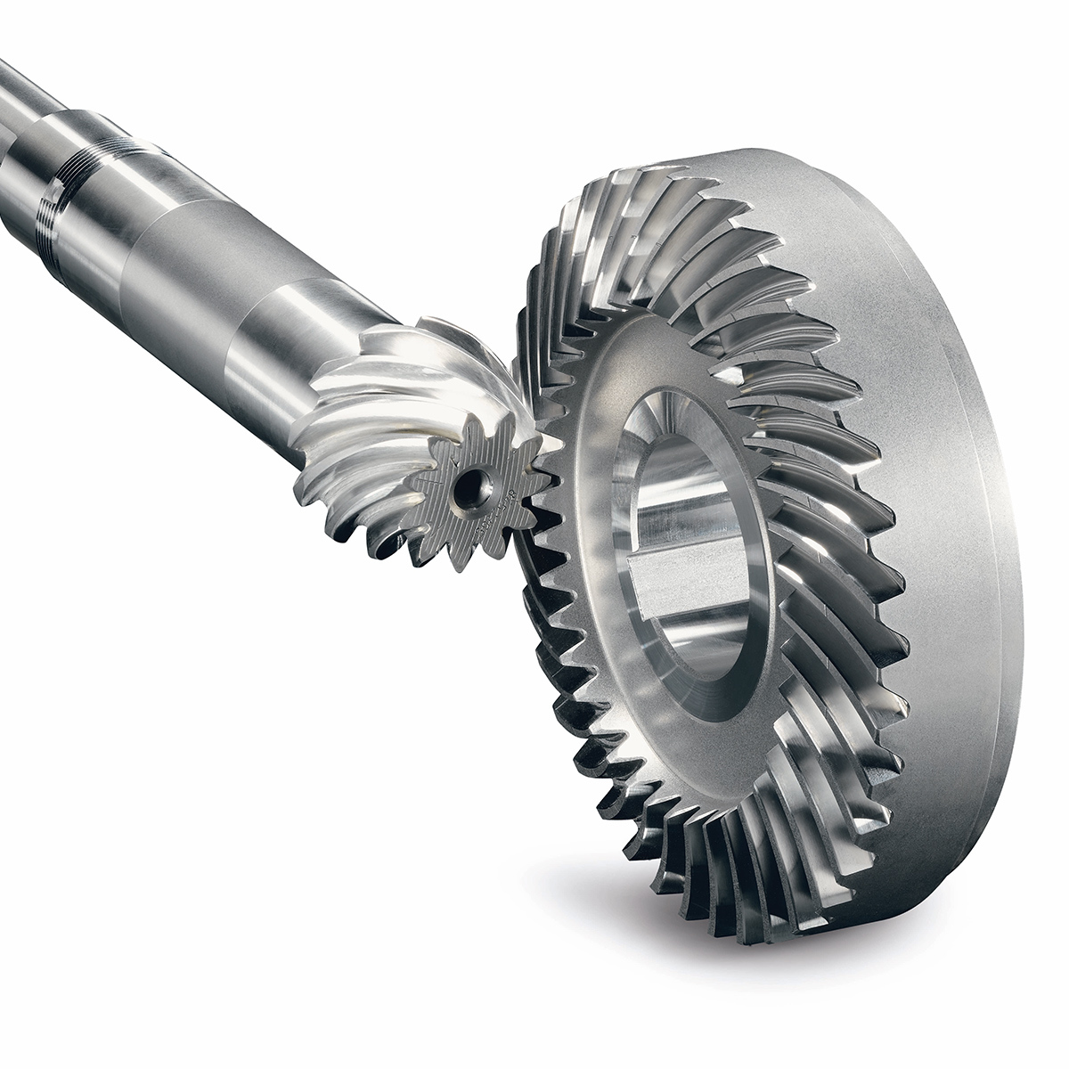
How do you install a bevel gear system?
Installing a bevel gear system involves several steps to ensure proper alignment, smooth operation, and efficient power transmission. Here’s a detailed explanation of how to install a bevel gear system:
- Preparation: Before installing the bevel gear system, gather all the necessary tools and equipment. Ensure that you have the correct bevel gears, shafts, bearings, and any additional components required for your specific application. Familiarize yourself with the system’s design, specifications, and installation instructions provided by the gear manufacturer.
- Clean and Inspect: Thoroughly clean all the components of the bevel gear system, including the gears, shafts, and bearings. Inspect them for any signs of damage, wear, or defects. Replace any damaged or worn-out parts to ensure optimal performance and longevity.
- Shaft Alignment: Proper alignment of the shafts is crucial for the bevel gear system’s performance. Ensure that the shafts are aligned accurately, both angularly and axially, as specified by the manufacturer. Misalignment can lead to premature wear, increased noise, and reduced efficiency. Use precision measurement tools, such as dial indicators, to achieve the required alignment.
- Bearing Installation: Install the bearings on the shafts according to the manufacturer’s instructions. Ensure that the bearings are securely fitted and properly lubricated. Proper bearing installation helps support the shafts, reduces friction, and ensures smooth rotation of the gears.
- Gear Meshing: Carefully position the bevel gears on the shafts, ensuring proper meshing between the teeth. The gear teeth should engage smoothly and evenly without any binding or excessive clearance. Achieving the correct gear meshing is crucial for efficient power transmission and to prevent premature wear or damage to the gears.
- Housing Assembly: Assemble the housing or casing that encloses the bevel gear system. Ensure that all housing components are aligned and securely fastened. Follow the manufacturer’s instructions for proper housing assembly, including the use of gaskets or seals to prevent lubricant leakage and contamination.
- Lubrication: Proper lubrication is essential for the smooth operation and longevity of the bevel gear system. Apply the recommended lubricant to the gears, bearings, and other moving parts according to the manufacturer’s specifications. Ensure that the lubricant used is compatible with the gear material, operating conditions, and environmental factors.
- Testing and Adjustment: After the installation is complete, perform a thorough system check. Rotate the shafts manually or using a suitable drive mechanism to ensure smooth gear operation, proper alignment, and absence of abnormal noise or vibration. Make any necessary adjustments, such as gear backlash or meshing depth, as per the manufacturer’s guidelines and based on the specific application requirements.
It’s important to note that the installation process may vary depending on the specific bevel gear system and application. Always refer to the manufacturer’s instructions and guidelines for the particular gear system you are working with to ensure proper installation and optimal performance.
In summary, installing a bevel gear system involves preparation, cleaning and inspection, shaft alignment, bearing installation, gear meshing, housing assembly, lubrication, and thorough testing and adjustment. Following proper installation procedures and adhering to manufacturer guidelines are essential to achieve efficient power transmission, smooth operation, and the desired performance from the bevel gear system.
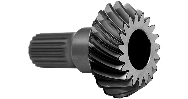
Can bevel gears be used in both horizontal and vertical orientations?
Yes, bevel gears can be used in both horizontal and vertical orientations, although certain considerations should be taken into account for each orientation. Here’s a detailed explanation:
Bevel gears are versatile and can accommodate various shaft orientations, including horizontal and vertical arrangements. The suitability of bevel gears for a specific orientation depends on factors such as load distribution, lubrication, and potential effects of gravity. Here are some considerations for each orientation:
- Horizontal Orientation: In horizontal applications, where the shafts are parallel to the ground, bevel gears can be used effectively. Proper lubrication is crucial to ensure adequate film formation and minimize friction and wear. Horizontal orientation typically allows for good load distribution among the gear teeth, promoting even wear and reducing the risk of localized stress concentrations. However, it is important to consider the effects of axial forces and thrust loads that may be present in the system and ensure that the gear design and bearings can handle these loads appropriately.
- Vertical Orientation: When bevel gears are used in a vertical orientation, where the shafts are perpendicular to the ground, additional considerations come into play. Gravity can introduce new challenges, such as the potential for gear thrust loads, lubricant pooling, and inadequate load distribution. To address these challenges, steps can be taken, including incorporating thrust bearings or thrust plates to handle axial forces, optimizing gear design to ensure proper load sharing, and implementing suitable lubrication methods to prevent lubricant pooling and ensure consistent lubrication to all gear surfaces. Additionally, proper sealing measures may be necessary to prevent lubricant leakage in the vertical orientation.
Overall, by considering the specific requirements and challenges associated with each orientation, bevel gears can be successfully utilized in both horizontal and vertical arrangements. Careful attention to design, lubrication, load distribution, and thrust management can help ensure reliable and efficient operation in either orientation.
It is important to note that for certain extreme or specialized applications, additional considerations and modifications may be required to accommodate the specific demands of the gear system. Consulting with experienced engineers and considering application-specific factors will help determine the most suitable gear design and orientation for a given application.
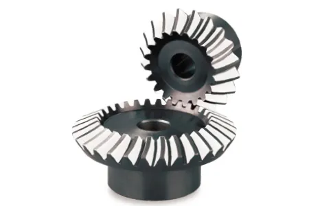
What is a bevel gear and how does it work?
A bevel gear is a type of gear that has teeth cut on the cone-shaped surface of the gear. It is used to transmit rotational motion and power between two intersecting shafts. Here’s a detailed explanation of what a bevel gear is and how it works:
A bevel gear consists of two cone-shaped gears with intersecting axes. The gear teeth are cut on the tapered surface of the gears. The gear with the smaller diameter is called the pinion, while the gear with the larger diameter is called the crown gear or ring gear.
Bevel gears are classified into different types based on their tooth geometry and arrangement. The most common types are straight bevel gears, spiral bevel gears, and hypoid bevel gears. Straight bevel gears have straight-cut teeth and intersect at a 90-degree angle. Spiral bevel gears have curved teeth that are gradually cut along the gear surface, allowing for smoother engagement and reduced noise. Hypoid bevel gears have offset axes and are used when the intersecting shafts are non-parallel.
When two bevel gears mesh together, the rotational motion from one gear is transmitted to the other gear. The gear teeth engage and disengage as the gears rotate, transferring torque and power between the shafts.
The operation of bevel gears is similar to that of other types of gears. When the pinion gear rotates, it causes the crown gear to rotate in the opposite direction. The direction of rotation can be reversed by changing the orientation of the gears. Bevel gears can provide different speed ratios and torque conversions depending on the gear sizes and the number of teeth.
The key characteristics of bevel gears include:
- Transmission of motion: Bevel gears are used to transmit rotational motion between intersecting shafts, allowing for changes in direction and speed.
- Torque transfer: Bevel gears can transmit torque from one shaft to another, allowing for power transmission in various mechanical systems.
- Axial thrust: Due to the angled tooth arrangement, bevel gears generate axial thrust forces that need to be properly supported or accounted for in the design of the mechanical system.
- Efficiency and noise: The efficiency and noise characteristics of bevel gears depend on factors such as tooth design, lubrication, and manufacturing quality.
Bevel gears are commonly used in a wide range of applications, including automotive differentials, power tools, printing presses, machine tools, and marine propulsion systems. Their ability to transmit motion and torque at intersecting angles makes them versatile and suitable for various mechanical systems.
In summary, a bevel gear is a cone-shaped gear that transmits rotational motion and power between intersecting shafts. It works by meshing the gear teeth of two gears, allowing for the transfer of torque and rotational motion. Bevel gears are available in different types and are used in various applications that require changes in direction or speed of rotational motion.


editor by CX 2023-09-25