
5
Bevel Gear Types Covered
96–99%
Spiral Bevel Efficiency
30–50mm
Typical Hypoid Offset
GL-5
Required Hypoid Lubricant
Table of Contents
02 — Core Geometry: What Makes Hypoid Different
03 — All Five Bevel Gear Types Explained
04 — Head-to-Head Technical Comparison
05 — Innovative Design Features
06 — Manufacturing Process
07 — Materials & Metallurgy
08 — Lubrication: The Critical Difference
09 — Industry Applications
10 — Compatibility & Interchangeability
11 — Replacement Guide
12 — Maintenance Best Practices
13 — Market Price Comparison
14 — Components & Accessories
15 — Sustainability & Compliance
16 — Case Studies
17 — Brand Comparison
18 — Customer Reviews
19 — FAQ
01
Understanding the Bevel Gear Family — Where Hypoid Fits In
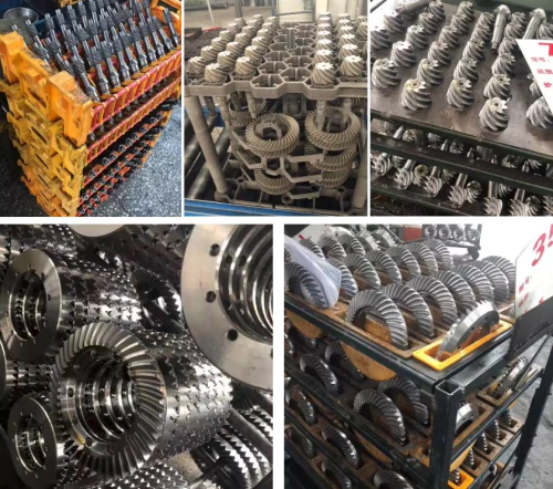
The phrase “bevel gear” describes a broad family of gears sharing one defining characteristic: conical pitch surfaces that allow torque transmission between shafts whose axes intersect — or, in the case of hypoid gears, nearly intersect — at an angle. What makes this family so valuable across engineering disciplines is precisely this ability to change the direction of a power flow, something that parallel-shaft gear types such as spur gears and helical gears fundamentally cannot accomplish within a single gear stage.
Hypoid gears are members of the bevel gear family, but they sit at a specific, distinct point within it. Their tooth geometry and manufacturing process are closely related to spiral bevel gears, yet the shaft geometry they operate on is fundamentally different. Confusing hypoid gears with standard spiral bevel gears — or treating them as interchangeable — is a technical error with real consequences for gear set life, noise performance, and lubricant selection.
This article works through the complete comparison: what bevel gears are as a category, where hypoid gears sit within that category, how their geometry and performance differ, and how to select between them for a given application. The discussion covers all five principal bevel gear types — straight bevel, spiral bevel, hypoid, zerol bevel, and mitre gears — with particular depth on the bevel-vs-hypoid distinction that most general references treat only superficially.
Australia Ever-Power supplies all bevel gear types from Condell Park NSW to engineering and manufacturing customers across Australia and the Asia-Pacific. For application-specific advice on gear type selection, contact the technical team at [email protected].
02
Core Geometry: The Single Feature That Separates Hypoid from All Other Bevel Gears
The Shaft Intersection Principle
In every bevel gear type except hypoid gears, the axes of the mating gear and pinion shaft — if extended — meet at a single point. This apex point is the cornerstone of all bevel gear geometry: the pitch cones of both gears share this apex, and the entire tooth geometry radiates from it. Straight bevel gears, spiral bevel gears, zerol bevel gears, and mitre gears all operate on this intersecting-axis principle. The shaft angle — most commonly 90 degrees — describes the angle between these two intersecting axes.
The Hypoid Offset — What Changes Everything
In a hypoid gear set, the pinion axis does not pass through the ring gear axis. The two axes are offset — typically by 30 to 50 mm in passenger car differentials — so that they are neither intersecting nor parallel: they are skew axes. This offset is described by a single number, the offset distance or hypoid offset, which is the perpendicular distance between the two shaft centrelines. The consequence of this seemingly small geometric change is profound: it affects tooth contact mechanics, lubrication requirements, load capacity, pinion size, shaft bearing loads, and manufacturing process.
Why the Offset Was Invented
The hypoid offset was developed deliberately in the early 1920s as a solution to a packaging problem in the automotive rear axle. By offsetting the pinion below the ring gear centreline, the propeller shaft connecting the gearbox to the rear differential could be positioned lower in the vehicle body. This allowed a flatter floor in the passenger compartment — an important comfort and styling benefit as enclosed-body automobiles became the standard. Packard Motor Car Company introduced the first hypoid rear axle in 1926, and within two decades the configuration had become universal in passenger car rear axle design.
Beyond packaging, the offset also enables a larger pinion for any given gear ratio, because the pinion no longer needs to fit geometrically within the constraints of intersecting-axis bevel gear proportions. A larger pinion means more teeth, greater tooth strength, and higher torque capacity — which is why hypoid gears are favoured in high-torque rear axle applications and heavy commercial vehicle drive axles where power density is at a premium.
03
All Five Bevel Gear Types — Complete Technical Profiles
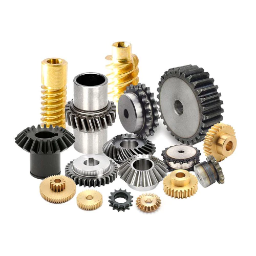
Before comparing bevel gears and hypoid gears directly, it is necessary to understand where each member of the bevel gear family stands. The five primary types each occupy a distinct performance niche within this gear family.
04
Head-to-Head Technical Comparison — Bevel Gears vs Hypoid Gears
The table below provides a direct parameter-by-parameter comparison between the bevel gear family (using spiral bevel as the representative high-performance type) and hypoid gears — the two types most commonly confused with each other in specification and purchasing decisions.
TR = Tapered Roller Bearings. ★ = Most commonly compared pair in specification decisions.
05
Innovative Design Features — What Sets Modern Bevel and Hypoid Gears Apart
Tooth Micro-Geometry Optimisation
Modern bevel gear design extends well beyond basic macro-geometry — module, tooth count, pressure angle, and spiral angle. Tooth micro-geometry modifications — intentional, controlled deviations from the theoretical tooth form in the profile and lead directions — are now routinely applied to both spiral bevel and hypoid gears to manage the shift of the contact ellipse under elastic deflection of shafts, bearings, and housing under operating load. These modifications, sometimes called “ease-off topography,” ensure that as the gear set deflects under load, the contact ellipse remains centred on the tooth face rather than migrating to the edge, where catastrophic stress concentrations would occur. Generating this ease-off through CNC bevel gear cutting machine settings — rather than through hand-lapping corrections — is a capability that distinguishes premium gear design from commodity production.
Torque-Vectoring and Active Differential Technology
Advanced automotive differentials now go beyond the passive speed-equalising function of a conventional open differential. Torque-vectoring differentials use electronically controlled clutch packs or planetary gear stages in combination with the fundamental hypoid ring-and-pinion to actively distribute torque between the two driven wheels — sending more torque to the outer wheel during cornering to improve handling, or directing torque to the wheel with better traction during off-road use. The hypoid gear set at the centre of these systems is identical in principle to a conventional differential, but the housing and control systems around it are substantially more complex. The precision and reliability of the hypoid gear set is a prerequisite for the functioning of these advanced drive dynamics systems.
CNC Face-Hobbing and Digital Twin Verification
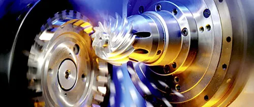
The most significant recent innovation in spiral bevel and hypoid gear manufacturing is the proliferation of CNC face-hobbing machines (such as the Gleason Phoenix series and equivalent platforms) that produce gear teeth in a continuous, fully numerically controlled process. These machines generate the complete tooth form — including all micro-geometry modifications — from a digital tooth file, rather than from mechanical cams and settings as older generation machines required. This digital control allows rapid switching between gear designs on a single machine, enables direct feedback from CMM measurement into the cutting process, and supports the use of digital twin models that predict the contact pattern and transmission error of a gear set before any physical cutting takes place. The result is faster development cycles, tighter production tolerances, and more consistent NVH performance in the finished differential.
DLC and Advanced Surface Coatings
Diamond-like carbon (DLC) coatings, applied by physical vapour deposition (PVD), are increasingly used on hypoid pinions and in some bevel gear applications where scuffing resistance in marginal lubrication conditions is critical. DLC coatings reduce the coefficient of friction at the tooth contact zone, protecting the surface during cold-start conditions (before the lubricant has fully warmed to operating viscosity) and providing a second line of defence in the event of lubricant contamination or depletion. While not yet universal in production hypoid gear sets, DLC coating is standard in several high-performance automotive and motorsport applications and is increasingly specified by industrial gear designers for aggressive duty-cycle applications in Australia’s mining and resources sector.
06
Manufacturing Process — From Steel Billet to Finished Gear Set
The production sequence for both spiral bevel gears and hypoid gears follows the same general stages. Differences arise primarily in the bevel gear cutter tools and machine settings used for the tooth cutting operation, and in the specific lapping or grinding requirements that follow heat treatment. The steps below describe the full production route for a high-quality case-hardened gear set of either type.
Steel Billet Selection & Forging
Alloy steel billets (AISI 8620, 9310 for carburised gears; AISI 4140 for through-hardened) are selected and ultrasonically tested for internal defects. Closed-die forging to blank shape refines the grain structure and improves fatigue properties. Normalising heat treatment relieves forging stresses before rough machining. For hypoid pinions, the forging die must accommodate the offset shaft geometry.
CNC Turning & Bore Machining
CNC lathes produce the outer cone profile, bore, keyway or spline, and back face to within grinding allowance. Bore concentricity established here is the reference datum for all subsequent tooth machining operations. For ring gears, the flange face and bolt hole circle are also completed at this stage. Surface finish requirements are tighter for spiral bevel than for straight bevel blanks due to the precision demands of the subsequent cutting operation.
Gear Tooth Cutting
The defining operation. Straight bevel gears are cut by Coniflex-style twin-cutter or form-milling processes. Spiral bevel and hypoid gears are cut by face milling (one tooth space per index) or face hobbing (continuous rotation) on CNC Gleason-type machines. Bevel gear cutter tools — circular face-mill cutter heads with carbide or HSS blade inserts — must be maintained to exacting tolerances. The CNC machine settings, derived from the digital tooth file, control every aspect of the resulting tooth geometry.
Carburising & Controlled Quenching
Gear sets are placed in continuous or batch carburising furnaces at 920–950°C in a controlled carbon-rich atmosphere for 4–12 hours depending on required case depth (typically 0.8–1.5 mm). Press quenching — clamping the hot gear in a die during oil quenching — controls distortion and minimises post-hardening correction requirements. Tempering at 160–180°C stabilises the martensite. 100% hardness verification follows: 58–62 HRC surface, 32–38 HRC core.
Hard Finishing — Lapping or Grinding
Automotive and industrial spiral bevel and hypoid gears are typically finish-processed by gear lapping (running the matched pair together with fine abrasive compound, achieving Ra 0.2–0.4 µm tooth finish and optimal contact pattern for the matched set) or by CNC tooth grinding on Gleason or Höfler machines (CBN or conventional grinding, achieving AGMA 12–13 quality). Lapping produces a matched pair that must stay together; grinding produces individually accurate gears that can be matched to any partner of the same specification.
CMM Inspection & Contact Pattern Test
Each gear is inspected on a coordinate measuring machine verifying tooth profile, lead, pitch, total helix deviation, runout, and surface finish against drawing tolerances. Matched pairs undergo contact pattern testing with marking compound under controlled load: the contact ellipse must be centred on the tooth face, slightly toward the toe under light load (to shift to the face centre under operating load). A full dimensional report accompanies every matched gear set shipped from Australia Ever-Power.
07
Bevel Gear Materials — Selection for Performance and Environment
Steel Alloys for High-Performance Applications
The dominant material for spiral bevel gears and hypoid gears in demanding applications is case-hardened alloy steel. AISI 8620 (a nickel-chromium-molybdenum alloy) is the workhorse of automotive and general industrial gear production — its combination of good machinability, carburising response, and adequate core toughness makes it the default for ring gears in medium-duty applications. AISI 9310, with higher nickel content, provides superior core toughness and is the standard for hypoid pinions (which carry higher cycle counts than ring gears), helicopter gearboxes, and defence equipment. Vacuum arc remelted (VAR) versions of AISI 9310 are specified for aerospace applications where inclusion-initiated fatigue is a life-limiting concern. AISI 4340 in through-hardened form serves medium-large industrial bevel gear applications where the full case-hardening route is not economically justified.
Stainless Steel and Bronze for Special Environments
316L and 17-4 PH stainless steels serve applications where corrosion resistance overrides maximum load capacity — food processing conveyor drives, pharmaceutical equipment, marine instrument drives, and chemical plant auxiliaries. Phosphor bronze (C91700) paired with a hardened steel pinion produces a classic “sacrificial” bevel gear pair where the bronze gear absorbs most of the wear, protecting the steel pinion and providing natural corrosion resistance and good sliding properties. This pairing is widely used in marine steering gear, valve actuators, and lightly-loaded industrial drives where frequent adjustment maintenance can replace the worn bronze gear at low cost.
Engineering Polymers for Light-Duty Applications
Acetal (POM), nylon (PA66, PA12), and glass-filled variants serve small, lightly-loaded straight bevel and mitre gear applications in instruments, consumer electronics, medical devices, and light automation. Their self-lubricating properties, electrical non-conductivity, chemical inertness, and very low unit cost from injection moulding make them attractive where loads are low enough for polymer teeth. PEEK offers the upper end of polymer performance — service temperatures to 250°C, excellent chemical resistance — but at significantly higher cost than standard engineering polymers. None are suitable for hypoid gears, which require the surface hardness and toughness of carburised steel to handle the sliding contact loads inherent to the hypoid tooth mesh.
08
Lubrication — The Critical Chemical Difference Between Bevel and Hypoid Gears
⚠️
Critical Warning: Lubricant Type Is Not Interchangeable
Using GL-4 gear oil in a hypoid differential application — even for a short period — can cause irreversible adhesive wear (scuffing) of the hypoid gear teeth. The API service category of the lubricant must match the gear type. This is not a “better safe than sorry” recommendation — it is a hard engineering requirement driven by the physics of the hypoid tooth contact zone.
The fundamental reason for the lubrication distinction is the sliding contact that occurs in hypoid gears due to the pinion axis offset. In a spiral bevel gear set, tooth contact is predominantly rolling, with only a small sliding component at the tooth tip and root as the contact ellipse traverses the tooth surface. In a hypoid gear set, the geometry of the offset axes introduces a longitudinal sliding velocity between the tooth surfaces — teeth slide against each other along their length as well as rolling across the profile. This combined rolling-and-sliding contact under high contact pressure generates surface temperatures that conventional gear oils cannot manage without severe tooth surface distress.
API GL-5 lubricants address this problem through sulphur-phosphorus extreme-pressure (EP) additives that react with the metal surface at elevated temperatures to form a thin protective iron sulphide or iron phosphate reaction layer. This layer acts as a solid-phase lubricant when the hydrodynamic oil film collapses under the high contact pressure of hypoid tooth sliding, preventing metal-to-metal contact and the adhesive wear that follows. The reaction is thermally triggered — the EP additives do not activate at normal operating temperatures, only at the localised high temperatures generated in the sliding contact zone. This is why the lubricant service category matters: a GL-4 oil has fewer EP additives and cannot form an adequate reaction layer under hypoid conditions.
Lubricant Selection Guide
One further caution specific to hypoid vehicles: GL-5 sulphur-phosphorus EP lubricants are corrosive to brass and bronze components at sustained high temperatures. Never use GL-5 gear oil in a manual gearbox fitted with brass synchroniser rings — the EP additives will rapidly corrode the synchroniser cones, destroying them. In most rear-wheel-drive vehicles, the differential and gearbox are separate, independent oil fills and this confusion should not arise. However, some transaxle designs share a common oil fill — check the vehicle service manual before specifying lubricant grade.
09
Industry Applications — Where Each Gear Type Operates
Bevel gear applications span virtually every engineering sector. Hypoid gears are concentrated primarily in automotive and heavy vehicle drivetrains, while the broader bevel gear family appears across an enormous diversity of machines and industries. Below is a sector-by-sector breakdown.
🚗 Automotive & Light Commercial
Hypoid gears: rear axle differential ring-and-pinion, 4WD transfer case, front axle differentials in AWD systems. Spiral bevel gears: transfer case internal stages, some front axle differentials. Straight/spiral bevel: differential spider gears and side gears within the carrier. The automotive differential is by far the highest-volume application for hypoid gears globally, with several hundred million sets in service worldwide.
🚛 Heavy Commercial & Off-Highway
Hypoid gears: drive axle final drives in Class 6–8 trucks, mining haul trucks, articulated dump trucks, and heavy off-highway equipment. The higher torque capacity of hypoid gears — enabled by the larger pinion from the axis offset — is the primary selection driver here. Spiral bevel: intermediate gearbox stages within axle assemblies and transfer cases. Reliability and service life measured in millions of km are design targets.
✈️ Aerospace & Defence
Spiral bevel gears (AGMA 13+, VAR steel): helicopter main gearbox, tail rotor gearbox, aircraft accessory drive gearboxes, military vehicle final drives. Zerol bevel gears: aircraft instrument drives, avionics actuators. Hypoid gears are less common in aerospace due to the EP lubricant requirement and the availability of alternative configurations. Weight and reliability are the dominant design drivers — no gear can fail in flight.
⛏️ Mining & Resources
Spiral bevel gears (large module, alloy steel): overland conveyor right-angle drive heads, longwall shearer cutting head drives, continuous miner drives, dragline rigging drums. Straight bevel gears: some auxiliary conveyor drives and low-speed ancillary equipment. In Australian mining — a dominant sector for Australia Ever-Power — the requirement for long service life between planned maintenance shutdowns drives gear quality specifications significantly above minimum.
🌾 Agriculture
Straight bevel gears: tractor PTO gearboxes, mower drives, baler mechanisms, rotary tillers. Spiral bevel gears: premium combine harvester header drives, high-power forage harvesters. Agricultural bevel gear differential mechanisms in tractor limited-slip rear axles use straight bevel spider/side gears. The combination of seasonal-peak operating loads, shock loading from field debris, and outdoor storage drives the need for robust materials and adequate lubrication maintenance.
🍽️ Food & Pharmaceutical
Stainless steel spiral/straight bevel and mitre gears: conveyor right-angle drives, mixer gearboxes, filling line drives, blender gearboxes. NSF H1 food-grade lubricants are mandatory in direct-contact zones. EHEDG hygiene-design compliant housings with IP69K protection for wash-down. The food sector does not use hypoid gears — the EP lubricants required are not food-safe, and the application loads do not justify hypoid geometry.
🤖 Robotics & Automation
Zerol bevel and precision spiral bevel gears (AGMA 12–13): articulated robot wrist joints, SCARA elbow drives, AGV steering drives, coordinate measuring machine axes. Low backlash, high stiffness, and repeatable positioning accuracy are the key requirements. Compact housings, lightweight aluminium carrier structures, and pre-lubricated sealed designs for maintenance-free operation are standard. Hypoid gears are occasionally used in robot base-rotation drives where high torque density justifies the EP lubricant requirement.
🌊 Marine & Offshore
Spiral bevel / hypoid gears: outboard lower unit drives, sterndrive Z-lower unit, vessel azimuth thruster drives. Corrosion-resistant alloy steel with appropriate coatings, sealed housings to prevent seawater ingress, and synthetic marine gear oils specified for wide temperature ranges in Australian coastal conditions from tropical north to sub-Antarctic south. Offshore ROV thrusters and underwater tooling drives use sealed stainless bevel gear stages for maximum corrosion immunity.
10
Compatibility & Interchangeability — What Can and Cannot Be Substituted
Hypoid Gears Are NOT Interchangeable with Spiral Bevel Gears
This is the most important compatibility rule in this entire article. Even if a hypoid ring gear and a spiral bevel ring gear share the same outer diameter, module, and tooth count, they cannot be meshed with each other’s pinion. The tooth profiles are different — generated by different machine settings to account for the different shaft geometry — and the mounting distances are different. Attempting to substitute a spiral bevel pinion for a hypoid pinion (or vice versa) in an otherwise unchanged housing produces immediate catastrophic tooth contact and gear failure. When replacing differential gears in any vehicle or industrial application, always confirm whether the original is a hypoid or a standard spiral bevel configuration before ordering replacements.
Gleason vs Klingelnberg: System Incompatibility
Beyond the hypoid/spiral bevel distinction, two major tooth geometry systems — Gleason (dominant in North America, Australia, Japan, and most of Asia) and Klingelnberg or Oerlikon (dominant in Europe) — produce gears that are geometrically incompatible with each other. A Gleason-system ring gear can only be correctly meshed with a Gleason-system pinion. When sourcing replacement gears for European-manufactured equipment, the cutting system must be identified first. Australia Ever-Power can assist with system identification from gear sample measurements or equipment documentation.
What IS Compatible: Within-System Replacements
Within a given gear system (e.g. Gleason spiral bevel, or Gleason hypoid), ring and pinion sets of the same specification — same tooth counts, same module, same pressure angle, same spiral angle, same system — can be replaced as matched pairs. The critical rule is that ring gear and pinion must always be replaced together, never individually. Lapped automotive differential pairs are a single matched component and must be treated as such. Precision-ground industrial gear sets, if produced to the same specification without lapping, may theoretically be matched to different partners, but this should only be done with contact pattern verification confirming correct mesh.
11
Replacement Guide — Bevel Gear and Hypoid Gear Replacement Step by Step
Before You Order: Information to Gather
A successful gear replacement starts with correct specification. For bevel gears in industrial equipment, gather: the number of teeth on gear and pinion; module or diametral pitch; pressure angle; spiral angle and direction (left-hand or right-hand); shaft angle; face width; bore diameter and keyway or spline dimensions; material and heat treatment; quality grade; and whether the gear was Gleason or Klingelnberg system. For automotive hypoid differentials, the vehicle make, model, year, and axle ratio (stamped on the differential cover or door jamb placard) typically identifies the gear set uniquely — contact Australia Ever-Power for cross-reference assistance.
Step-by-Step Replacement Procedure
12
Bevel Gear Maintenance — Scheduled Intervals and Condition Monitoring
The bevel gear maintenance programme for any given installation should be designed around the application severity, the cost of unplanned downtime, and the accessibility of the unit for inspection. The schedule below provides a baseline that covers the vast majority of industrial and automotive applications. More demanding duty cycles — continuous 24/7 operation, high shock loading, extreme temperature ranges — justify shorter inspection intervals throughout.
🔍 Daily — Visual Check
Inspect for oil leakage at shaft seals and housing joints. Listen for any unusual noise or vibration change during operation startup. Check housing temperature by touch if no thermometer is fitted — should not be hot enough to be uncomfortable to hold.
📋 Monthly — Oil Level & Sample
Check oil level at sight glass or dipstick. Draw a small oil sample and inspect visually for milky discolouration (water contamination), metallic particles, or darkening (oxidation). Check magnetic drain plug for metallic debris buildup — an early indicator of wear rate increase.
🛠️ Annual / 2,500 hrs — Full Service
Drain and replace gear oil. Replace shaft seals. Inspect gear teeth through inspection cover for pitting, scuffing, or wear pattern migration. Send oil sample to a laboratory for wear metal analysis. Record results and trend against previous samples — rising iron or nickel content indicates accelerating wear.
🔧 Major Overhaul — 5,000+ hrs
Full disassembly and dimensional inspection of gear set and all bearings. Replace bearings regardless of apparent condition. Re-check contact pattern. Measure backlash against original specification — excessive backlash indicates worn gear or bearing journal. Reassemble with new seals, correct lubricant fill, and documented re-commissioning checks.
Failure Warning Signs — Act Before Catastrophic Failure
The following symptoms indicate gear system distress and require immediate investigation: a speed-dependent whine or howl not present in normal operation; a periodic clunking during torque reversal (drive to overrun); vibration through the machine structure at the gear mesh frequency; abnormally high housing temperature; metallic particles visible in drained oil; or any sudden change in noise character during operation. Early intervention — typically requiring only an oil change or bearing replacement — avoids the far greater cost of gear set replacement and extended downtime.
13
Market Price Comparison — Bevel Gear and Hypoid Gear Pricing in Australia
Bevel gear pricing varies significantly by type, size, material, quality grade, and quantity. The table below provides indicative AUD price ranges for common configurations available in the Australian market. All prices are for matched gear and pinion pairs from a reputable supplier with full material certification at moderate quantities (10–50 units).
* Indicative AUD prices for moderate quantities with full material certification. Contact [email protected] for a precise quotation on your specific requirements.
Hypoid gear sets carry a price premium over equivalent-size spiral bevel gears — typically 20–40% — primarily because the more complex geometry requires additional machine programming and setup time, and because automotive-grade hypoid production at non-automotive volumes cannot achieve the same economies of scale as high-volume passenger car differential production. For industrial applications where the hypoid offset is not mechanically required, spiral bevel gears are the more cost-effective choice at equivalent load ratings.
14
Related Components & Accessories
A bevel gear set — whether spiral bevel or hypoid — never operates in isolation. The following components are routinely specified alongside bevel gears and form an integrated drive system that determines the overall performance and service life of the installation.
- ▸
Tapered Roller Bearings: The standard bearing for spiral bevel and hypoid gear shafts, capable of handling combined radial and axial (thrust) loads. Must be correctly preloaded during assembly — excessive preload generates heat; insufficient preload allows axial play that shifts the contact pattern.
- ▸
Angular Contact Ball Bearings: Used in precision bevel gear assemblies for lighter loads where lower noise and higher-speed capability are required. Common in robotics and precision machine tool applications.
- ▸
Gear Housing / Differential Carrier: The ductile iron, steel, or aluminium alloy housing that positions gear and pinion at the correct mounting distance and cone distance. Housing rigidity directly determines contact pattern stability under load.
- ▸
Shim Sets (Adjusting Shims): Precision-ground shim stacks used to set the mounting distance, cone distance, and bearing preload during assembly. Critical to correct contact pattern and backlash achievement — a shim error of 0.05 mm can move the contact ellipse significantly.
- ▸
Rotary Shaft Seals (Lip Seals): Prevent lubricant leakage and contamination ingress at rotating shaft exits. The pinion oil seal is the highest-wear seal in a differential and the primary cause of lubricant loss — replace at every gear set replacement.
- ▸
GL-5 / GL-4 Gear Lubricants: The correct lubricant is not optional equipment — it is a functional component of the gear drive system. Synthetic GL-5 (75W-90 or 75W-140) for hypoid; GL-4 or GL-5 ISO VG 220–320 for spiral bevel industrial gearboxes.
- ▸
Bevel Gear Cutter Tools: Circular face-mill cutter heads with carbide inserts, used in Gleason-type cutting machines for production of spiral bevel and hypoid gear teeth. Must be maintained and reconditioned regularly to sustain tooth geometry accuracy.
- ▸
Magnetic Drain Plugs: Fitted to gear housings to capture ferrous wear particles in the oil sump. The quantity of particles on the magnetic plug at each oil change is a simple, cost-free condition monitoring indicator of gear and bearing wear rate.
- ▸
Vibration & Temperature Sensors: Accelerometers and RTDs mounted on gear housings enable online condition monitoring, providing early detection of developing bearing or gear faults before they escalate to catastrophic failure — particularly valuable for remotely-located or difficult-to-access drives.
- ▸
Keyways, Splines & Couplings: The torque connection between gear bore and shaft must be correctly specified for the transmitted torque and duty cycle. Interference fit, key-and-keyway, involute spline, or hydraulic expansion coupling — each has different fatigue and fretting characteristics that must match the application demands.
Featured Product — Australia Ever-Power
Spiral Miter Bevel Gear — Precision 1:1 Right-Angle Drive
Manufactured to spiral bevel tooth geometry for smooth, quiet 1:1 directional drives. Ideal for food processing, robotic, and automation equipment requiring right-angle direction change without speed or torque alteration.
15
Sustainability, Global Markets & Regulatory Compliance
Key Producing and Consuming Markets
Bevel gears and hypoid gears are produced and consumed on every continent, but significant concentrations exist in specific regions. The United States, Germany, Japan, China, South Korea, and India account for the majority of global precision bevel gear production. Germany and Japan supply the majority of the world’s Gleason-compatible and Klingelnberg-compatible precision bevel gear cutting machine tools respectively, which underpins manufacturing globally. China has become the largest single producer of commodity-grade bevel gears for agricultural, light industrial, and automotive replacement markets. Australia is primarily a consuming market — the mining resources sector, automotive aftermarket, agricultural machinery sector, and general manufacturing industry collectively represent a substantial and growing demand base that Australia Ever-Power serves from Condell Park NSW.
Sustainability in Bevel Gear Manufacturing and Use
The sustainability profile of bevel gear products is driven primarily by three factors: the energy consumed in manufacturing, the efficiency of the gear drive in service (directly affecting the operating energy consumption of the machine it powers), and the service life achieved (which determines how frequently the gear set must be manufactured again). Precision spiral bevel and hypoid gears, with their higher manufacturing cost but superior service life and operating efficiency, deliver a significantly better lifecycle environmental footprint than lower-quality equivalents — even accounting for the additional manufacturing energy their production requires.
The transition to near-dry machining (minimal quantity lubrication, MQL) in bevel gear cutting reduces cutting fluid consumption and associated waste disposal costs. Induction hardening of straight bevel gears — where applicable — reduces energy consumption compared to batch furnace carburising. Shot peening of gear tooth roots to induce beneficial compressive residual stresses extends fatigue life without consuming additional material. Australia Ever-Power actively selects manufacturing partners who implement these sustainability practices.
Regulatory Standards and Compliance
In Australia, mechanical power transmission equipment is subject to the Work Health and Safety Act and Regulations, which require that gear drives in machinery be designed and maintained to prevent foreseeable mechanical hazard. Mobile plant and fixed plant in Australian mining operations must comply with the requirements of the relevant state mining regulations as well as AS 4024 (Safety of Machinery). The AGMA standard suite — AGMA 2003 for bevel gear rating, AGMA 9005 for industrial gear lubrication — is the reference framework used throughout the Australian industrial gear market. European-origin equipment must comply with the EU Machinery Directive (2006/42/EC) and is subject to DIN/ISO gear standards. Defence and aerospace gear supply chains require AS9100 quality certification. Australia Ever-Power provides full material documentation and can support customer compliance requirements including material test reports, first-article inspection reports, and conformance declarations.
16
Customer Success Stories & Case Studies
⛏️
WA Iron Ore Conveyor — Spiral Bevel Upgrade
850 kW overland conveyor drive, Pilbara WA
A Pilbara iron ore producer was experiencing repeated straight bevel gear failures in conveyor right-angle drive heads at 14-month intervals due to shock loading from ore surge events. Failure analysis identified tooth root fatigue as the mechanism. Australia Ever-Power specified a replacement using spiral bevel gears of the same module and ratio — capitalising on the superior face contact ratio and shock tolerance of the spiral form — paired with a revised synthetic EP lubricant fill. The first spiral bevel replacement set has now operated for 44 months without failure. The single replacement amortised the specification change cost within six months of installation.
Outcome: Gear life tripled. Estimated AUD $340,000 saved in replacement and downtime costs.
🚛
Heavy Haulage Fleet — Hypoid Differential Replacement
30-truck fleet, QLD resources region
A Queensland road transport company operating 30 Class 8 road trains in the resources corridor was suffering from accelerating hypoid differential failures across the fleet. Investigation revealed all failures traced to the same root cause: the fleet had been maintained using GL-4 gear oil instead of the specified GL-5 — a purchasing error that persisted across multiple oil changes. Australia Ever-Power supplied full replacement hypoid gear sets, confirmed the correct GL-5 specification, and provided an on-site technical briefing for maintenance staff on lubricant classification and consequences. No recurrence of the failure mode has been reported in 24 months of follow-up.
Outcome: Root cause eliminated. Fleet differential life now meeting OEM specification targets.
🍽️
Food Processing — Stainless Mitre Gear Conversion
Poultry processing facility, NSW
A NSW poultry processor operating a high-speed portioning line had persistent corrosion problems with carbon-steel straight bevel mitre gears in conveyor drives exposed to daily high-pressure caustic wash-down. Australia Ever-Power supplied 316L stainless steel spiral mitre gear pairs in sealed housings rated IP69K, filled with NSF H1 food-grade synthetic lubricant. After 18 months of daily wash-down operation, zero corrosion has been found on any gear set. The upgrade also reduced operating noise by approximately 8 dB(A) due to the switch from straight to spiral tooth form — a secondary benefit that improved the processing floor work environment.
Outcome: Zero corrosion in 18 months. 8 dB(A) noise reduction. Full HACCP compliance maintained.
17
Brand Comparison — How Australia Ever-Power Compares
The Australian bevel gear supply market includes international catalogue distributors, European premium brands, offshore-direct importers, and local specialists. The comparison below is factual and objective — it reflects the genuine strengths of each supply model and explains why Australia Ever-Power’s combination of attributes delivers the best total value for the majority of Australian engineering and maintenance buyers.
Australia Ever-Power is not the cheapest supplier in every category — that position belongs to offshore commodity importers who cannot offer material certification, engineering support, or short lead times. Nor is it priced at the European premium brand level. What it provides is the most complete combination of technical credibility, documentation rigour, short Australian lead times, and genuine application engineering support — attributes that matter most when gear failure has real operational and financial consequences.
18
Customer Reviews
“Replaced a worn hypoid differential gear set in a haul truck at one of our NT mine sites. Ever-Power was the only local supplier who could confirm the correct GL-5 specification, supply with full material certs, and ship inside a week. Every other option was quoting six to eight weeks from overseas. The gear set is now at 11 months with no issues. That lead time difference saved us a critical production window.”
— Damon Fairweather
Mechanical Superintendent · Mining Operations, NT
“I specifically needed a spiral bevel gear set — NOT hypoid — for an industrial right-angle gearbox where we cannot use GL-5 oil due to bronze bushings in the housing. The team at Ever-Power understood the distinction immediately and confirmed the correct spiral bevel configuration. Most suppliers I called either didn’t know the difference or tried to sell me a hypoid set regardless. That technical awareness alone is worth a premium.”
— Anita Radovanović
Senior Mechanical Engineer · Industrial Equipment OEM, VIC
“Ordered a set of zerol bevel gears for a pharmaceutical tablet press drive — stainless required, food-grade lube, tight backlash spec. The gear set arrived within two weeks with a complete dimensional inspection report and contact pattern photo. Fit and function were perfect on first assembly. Docking one star only because the initial quote response took three days rather than one — a very minor point given the quality of what arrived.”
— Marcus Tillotson
Project Engineer · Pharmaceutical Equipment, QLD
“Sourced a custom hypoid gear set for a marine azimuth thruster on a research vessel operating in Antarctic waters. The specification was complex — corrosion-resistant alloy, wide operating temperature range, and full classification society documentation. Ever-Power handled the complete specification process, coordinated with the class surveyor for approval, and delivered within the dry-dock schedule window. Genuinely impressed by the project management alongside the technical capability.”
— Capt. Fiona Ngata
Fleet Technical Manager · Marine Research Operations, TAS
19
Frequently Asked Questions — Bevel Gears & Hypoid Gears
Common technical and procurement questions answered by Australia Ever-Power’s engineering team.