
Product Description
Company Profile
Workshop
Detailed Photos
Product Description
| Material | Alloy Steel, Copper alloy(brass,silicon bronze,phosphor bronze,aluminum bronze,beryllium copper),Stainless Steel,Aluminum,Titanium, Magnesium, Superalloys,Molybdenum, Invar,,Zinc,Tungsten steel,incoloy,Nickel 200,Hastelloy, Inconel,Monel,ABS, PEEK,PTFE,PVC,Acetal. |
| Surface Treatment | Zn-plating, Ni-plating, Cr-plating, Tin-plating, copper-plating, the wreath oxygen resin spraying, the heat disposing, hot-dip galvanizing, black oxide coating, painting, powdering, color zinc-plated, blue black zinc-plated, rust preventive oil, titanium alloy galvanized, silver plating, plastic, electroplating, anodizing etc. |
| Producing Equipment | CNC machine,automatic lathe machine,CNC milling machine,lasering,tag grinding machine etc. |
| Drawing Format | Pro/E, Auto CAD, CHINAMFG Works, UG, CAD/CAM, PDF |
| Managing Returned Goods | With quality problem or deviation from drawings |
| Warranty | Replacement at all our cost for rejected products |
| Main Markets | North America, South America, Eastern Europe , West Europe , North Europe, South Europe, Asia |
| How to order | * You send us drawing or sample |
| * We carry through project assessment | |
| * We make the sample and send it to you after you confirmed our design | |
| * You confirm the sample then place an order and pay us 30% deposit | |
| * We start producing | |
| * When the goods is done, you pay us the balance after you confirmed pictures or tracking numbers. | |
| * Trade is done, thank you!! |
Quality Control
Packaging & Shipping
Customer Reviews
FAQ
Q1:What kind of information do you need for quotation?
A: You can provide 2D/3D drawing or send your sample to our factory, then we can make according to your sample.
Q2: Can we CHINAMFG NDA?
A: Sure. We can CHINAMFG the NDA before got your drawings.
Q3: Do you provide sample?
A: Yes, we can provide you sample before mass order.
Q4: How can you ensure the quality?
A: We have profesional QC,IQC, OQC to guarantee the quality.
Q5: Delivery time?
A: For samples genearlly need 25 days. Mass production: around 30~45 days after receipt of deposit (Accurate delivery time
depends on specific items and quantities)
Q6: How about the transportation?
A: You can choose any mode of transportation you want, sea delivery, air delivery or door to door express.
| Hardness: | Hardened Tooth Surface |
|---|---|
| Gear Position: | Internal Gear |
| Manufacturing Method: | Cut Gear |
| Toothed Portion Shape: | Spur Gear |
| Material: | Stainless Steel |
| Tolerance: | +/- 0.005mm, According to Your Specification |
| Customization: |
Available
| Customized Request |
|---|
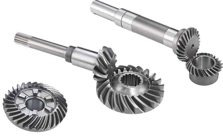
How does a bevel gear impact the overall efficiency of a system?
A bevel gear plays a significant role in determining the overall efficiency of a system. Its design, quality, and operating conditions can impact the efficiency of power transmission and the system as a whole. Here’s a detailed explanation of how a bevel gear can impact overall efficiency:
- Power Transmission Efficiency: The primary function of a bevel gear is to transmit power between intersecting shafts at different angles. The efficiency of power transmission through a bevel gear depends on factors such as gear geometry, tooth profile, material quality, lubrication, and operating conditions. In an ideally designed and well-maintained system, bevel gears can achieve high power transmission efficiency, typically above 95%. However, factors such as friction, misalignment, inadequate lubrication, and gear tooth wear can reduce efficiency and result in power losses.
- Friction and Mechanical Losses: Bevel gears experience friction between their mating teeth during operation. This friction generates heat and causes mechanical losses, reducing the overall efficiency of the system. Factors that affect friction and mechanical losses include the gear tooth profile, surface finish, lubrication quality, and operating conditions. High-quality gears with well-designed tooth profiles, proper lubrication, and optimized operating conditions can minimize friction and mechanical losses, improving the overall efficiency.
- Gear Tooth Design: The design of the bevel gear tooth profile influences its efficiency. Factors such as tooth shape, size, pressure angle, and tooth contact pattern affect the load distribution, friction, and efficiency. Proper tooth design, including optimized tooth profiles and contact patterns, help distribute the load evenly and minimize sliding between the teeth. Well-designed bevel gears with accurate tooth profiles can achieve higher efficiency by reducing friction and wear.
- Material Quality and Manufacturing Precision: The material quality and manufacturing precision of bevel gears impact their durability, smooth operation, and efficiency. High-quality materials with suitable hardness, strength, and wear resistance can minimize friction, wear, and power losses. Additionally, precise manufacturing processes ensure accurate gear geometry, tooth engagement, and alignment, optimizing the efficiency of power transmission and reducing losses due to misalignment or backlash.
- Lubrication and Wear: Proper lubrication is crucial for reducing friction, wear, and power losses in bevel gears. Insufficient or degraded lubrication can lead to metal-to-metal contact, increased friction, and accelerated wear, resulting in reduced efficiency. Adequate lubrication with the recommended lubricant type, viscosity, and replenishment schedule ensures a sufficient lubricating film between the gear teeth, minimizing friction and wear and improving overall efficiency.
- Misalignment and Backlash: Misalignment and excessive backlash in bevel gears can negatively impact efficiency. Misalignment causes uneven loading, increased friction, and accelerated wear. Excessive backlash results in power losses during direction changes and can lead to impact loads and vibration. Proper alignment and control of backlash within acceptable limits are crucial for maintaining high efficiency in a bevel gear system.
Overall, a well-designed bevel gear system with high-quality materials, accurate manufacturing, proper lubrication, and minimal losses due to friction, misalignment, or wear can achieve high efficiency in power transmission. Regular maintenance, monitoring, and optimization of operating conditions are essential to preserve the efficiency of the system over time.
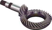
What are the potential challenges in designing and manufacturing bevel gears?
Designing and manufacturing bevel gears can present several challenges due to their complex geometry, load requirements, and manufacturing processes. Here’s a detailed explanation of the potential challenges:
When it comes to designing and manufacturing bevel gears, the following challenges may arise:
- Complex Geometry: Bevel gears have intricate geometry with non-parallel and intersecting tooth profiles. Designing bevel gears requires a thorough understanding of gear theory, tooth engagement, and load distribution. The complex geometry poses challenges in determining the optimal tooth profile, tooth contact pattern, and gear ratios for the specific application.
- Load Analysis and Distribution: Determining the correct load analysis and distribution is crucial to ensure the gears can handle the anticipated forces and torques. Bevel gears often encounter varying loads, including radial loads, axial loads, and bending moments. Accurately predicting and distributing these loads across the gear teeth is essential for achieving proper gear strength, minimizing wear, and preventing premature failure.
- Manufacturing Precision: Bevel gears require high manufacturing precision to ensure smooth operation, minimal backlash, and efficient power transmission. Achieving the required precision in gear manufacturing involves precise machining, grinding, and heat treatment processes. The complex geometry of bevel gears adds to the manufacturing complexity, necessitating specialized equipment and skilled operators.
- Alignment Challenges: Proper alignment of bevel gears is critical for optimal performance and longevity. Achieving accurate alignment can be challenging due to the non-parallel shafts and intricate tooth profiles. Misalignment can lead to increased noise, vibration, and premature wear. Design considerations for alignment, as well as careful assembly and alignment procedures during manufacturing, are necessary to address this challenge.
- Lubrication and Cooling: Bevel gears require effective lubrication to minimize friction, wear, and heat generation. Ensuring proper lubrication and cooling can be challenging due to the unique shape of bevel gears and the limited space available for lubricant circulation. Designing appropriate lubrication systems, selecting suitable lubricants, and considering heat dissipation methods are essential for maintaining optimal gear performance and preventing overheating.
- Quality Control: Maintaining consistent quality during the manufacturing process is crucial for reliable bevel gears. Implementing robust quality control measures, including dimensional inspections, surface quality assessments, and gear testing, helps ensure that the manufactured gears meet the specified requirements. Consistency in gear quality is essential to minimize variations in performance and to ensure accurate gear meshing and load distribution.
Addressing these challenges requires a combination of engineering expertise, advanced manufacturing techniques, and quality control processes. Collaborating with experienced gear designers, employing state-of-the-art manufacturing technologies, and conducting thorough testing and analysis can help overcome these challenges and produce high-quality bevel gears that meet the performance and durability requirements of the intended application.
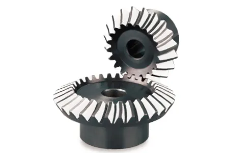
What is a bevel gear and how does it work?
A bevel gear is a type of gear that has teeth cut on the cone-shaped surface of the gear. It is used to transmit rotational motion and power between two intersecting shafts. Here’s a detailed explanation of what a bevel gear is and how it works:
A bevel gear consists of two cone-shaped gears with intersecting axes. The gear teeth are cut on the tapered surface of the gears. The gear with the smaller diameter is called the pinion, while the gear with the larger diameter is called the crown gear or ring gear.
Bevel gears are classified into different types based on their tooth geometry and arrangement. The most common types are straight bevel gears, spiral bevel gears, and hypoid bevel gears. Straight bevel gears have straight-cut teeth and intersect at a 90-degree angle. Spiral bevel gears have curved teeth that are gradually cut along the gear surface, allowing for smoother engagement and reduced noise. Hypoid bevel gears have offset axes and are used when the intersecting shafts are non-parallel.
When two bevel gears mesh together, the rotational motion from one gear is transmitted to the other gear. The gear teeth engage and disengage as the gears rotate, transferring torque and power between the shafts.
The operation of bevel gears is similar to that of other types of gears. When the pinion gear rotates, it causes the crown gear to rotate in the opposite direction. The direction of rotation can be reversed by changing the orientation of the gears. Bevel gears can provide different speed ratios and torque conversions depending on the gear sizes and the number of teeth.
The key characteristics of bevel gears include:
- Transmission of motion: Bevel gears are used to transmit rotational motion between intersecting shafts, allowing for changes in direction and speed.
- Torque transfer: Bevel gears can transmit torque from one shaft to another, allowing for power transmission in various mechanical systems.
- Axial thrust: Due to the angled tooth arrangement, bevel gears generate axial thrust forces that need to be properly supported or accounted for in the design of the mechanical system.
- Efficiency and noise: The efficiency and noise characteristics of bevel gears depend on factors such as tooth design, lubrication, and manufacturing quality.
Bevel gears are commonly used in a wide range of applications, including automotive differentials, power tools, printing presses, machine tools, and marine propulsion systems. Their ability to transmit motion and torque at intersecting angles makes them versatile and suitable for various mechanical systems.
In summary, a bevel gear is a cone-shaped gear that transmits rotational motion and power between intersecting shafts. It works by meshing the gear teeth of two gears, allowing for the transfer of torque and rotational motion. Bevel gears are available in different types and are used in various applications that require changes in direction or speed of rotational motion.


editor by CX 2023-09-18