
The Hypoid Gear: Not Just a Modified Bevel Gear
Most engineers who encounter hypoid gears initially assume they are simply spiral bevel gears with a minor geometric modification. This impression is understandable — hypoid gears look strikingly similar to spiral bevel gears, both featuring curved, helical teeth on conical blanks. But the difference — an offset between the pinion shaft centreline and the ring gear’s rotational axis — fundamentally changes the tooth contact mechanics in ways that create both significant advantages and equally significant constraints that must be understood before specifying this gear type.
The hypoid gear was developed in the early 20th century primarily for automotive rear axle differentials, where vehicle designers needed to lower the driveshaft and floor tunnel height without sacrificing power transmission capacity. The hypoid offset — typically 20–40% of the ring gear radius in automotive applications — allowed the pinion shaft to be positioned below the ring gear centreline, directly lowering the driveshaft height and consequently the vehicle’s centre of gravity and floor level. This single geometric change triggered the adoption of hypoid gears in nearly every rear-wheel-drive and four-wheel-drive passenger vehicle and truck produced since the 1920s.
Australia Ever-Power, in Condell Park NSW 2200, manufactures both hypoid and standard spiral bevel gear sets and assists customers with the selection decision when application requirements are unclear. The guidance in this article reflects genuine engineering practice — not a simplified rule-of-thumb approach.
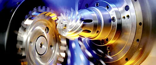
What the Shaft Offset Changes: The Mechanics of Hypoid Contact
The Geometric Consequence of Offset Shafts
In a spiral bevel gear set, both shaft centrelines extend to a common apex — the pitch cone apex. Every contact point on a tooth flank lies on a line passing through this apex. When the pinion shaft is offset from the ring gear centreline (as in a hypoid set), the tooth contact geometry can no longer be described by a simple cone — the pitch surface of the pinion is a hyperboloid of revolution (hence “hypoid”), a saddle-shaped surface that intersects the ring gear’s conical pitch surface along a curved line rather than a straight generator.
This hyperboloidal contact has a profound effect on tooth sliding velocities. In a spiral bevel gear, sliding at the tooth contact surface occurs primarily along the tooth height direction (profile sliding) with lesser sliding in the tooth length direction. In a hypoid gear, the offset creates a substantial additional sliding component along the tooth length — in the direction of the tooth lengthwise curve. This lengthwise sliding is what makes hypoid gears so sensitive to lubricant quality: the lengthwise sliding velocity can reach 5–15 m/s in automotive applications, requiring lubricants with far greater extreme pressure additive capability than standard spiral bevel gear oils.
The Larger Pinion Advantage
The offset geometry allows the hypoid pinion to have a significantly larger diameter than an equivalent spiral bevel pinion at the same gear ratio and ring gear size. A spiral bevel pinion at 4:1 ratio might have a pitch diameter of 60 mm against a 240 mm ring gear. A hypoid pinion at the same ratio, with a modest offset, might achieve 80–90 mm pitch diameter — a 33–50% increase. This larger pinion diameter means more tooth area in contact, better load distribution, higher bending strength at the tooth root, and reduced risk of undercut. The larger hypoid pinion typically has more teeth than the equivalent spiral bevel pinion at the same ratio, further increasing contact ratio and reducing noise.
Five Situations Where Hypoid Gears Are the Correct Choice
When the design requires the pinion shaft to be positioned below, above, or offset from the ring gear’s rotational axis — regardless of the specific offset distance — only hypoid gears can achieve this geometry. Any non-zero shaft axis offset requires hypoid geometry. This is the fundamental requirement in rear-wheel-drive vehicle axles, where the driveshaft must clear the vehicle floor structure. In industrial applications, shaft offset requirements arise from space constraints in the equipment housing where parallel shaft axes would conflict with adjacent components.
The larger hypoid pinion diameter at equivalent gear ratio means hypoid gear sets provide higher torque capacity per unit of overall gearbox volume compared to spiral bevel sets at the same ratio. When the design envelope is tight and the torque requirement is at the upper limit of what a standard spiral bevel set of the available size can achieve, upgrading to hypoid geometry — which allows a larger, stronger pinion — can increase the rating by 15–30% without increasing the gearbox housing diameter. This is a valuable option when retrofitting more powerful drives into existing equipment housings.
Hypoid gears, due to their larger pinion tooth count and higher total contact ratio compared to equivalent spiral bevel sets, can achieve lower transmission error and consequently lower noise levels than the best available spiral bevel configuration at the same gear ratio. For high-speed applications where noise is a primary design constraint — luxury vehicles, quiet indoor drive units, medical imaging equipment — the noise advantage of hypoid gears justifies their higher manufacturing complexity and lubrication requirements. The smoother, more gradual contact entry and exit of a hypoid tooth pair produces a quieter mesh signature than even a well-optimised spiral bevel set.
All modern passenger car, SUV, and truck rear-axle differentials use hypoid gears — not spiral bevel gears — because of the combined advantages of shaft offset (lower floor), larger pinion (higher strength), and lower noise. Replacement differentials for these vehicles must use hypoid gears — fitting a spiral bevel set would result in geometric incompatibility with the housing (the spiral bevel pinion shaft would be at the wrong height) and would provide lower torque capacity and higher noise than the original hypoid specification.
At gear ratios above approximately 5:1, the spiral bevel pinion becomes very small relative to the ring gear, limiting the minimum tooth count achievable without undercutting and reducing the pinion’s structural strength. The hypoid offset allows the pinion to maintain a larger diameter at high ratios — addressing the small-pinion problem directly. Hypoid gear sets at ratios of 6:1 to 12:1 are feasible in a single stage where equivalent spiral bevel sets would either be mechanically marginal or require an additional reduction stage.
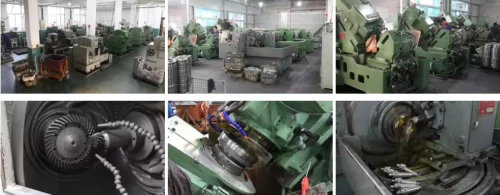
When Standard Spiral Bevel Gears Remain the Better Choice
Hypoid gears are more mechanically capable than spiral bevel gears in the five scenarios above, but they bring real engineering complications that make them the wrong choice in many applications. Understanding these limitations is as important as understanding the advantages:
⚠ Lubricant Sensitivity
Hypoid gears absolutely require hypoid-specific gear oil with GL-5 or higher EP rating. Using standard GL-4 oil — adequate for spiral bevel gears — in a hypoid application causes rapid scuffing of the tooth surfaces due to the high lengthwise sliding velocity. Many industrial gearboxes are routinely maintained with “general purpose gear oil” that is inappropriate for hypoid use.
⚠ Manufacturing Complexity
Hypoid gears require the same Gleason face-milling equipment as spiral bevel gears but with more complex machine settings to define the offset geometry correctly. The risk of error in the machine setup is higher, and first-off verification by contact pattern check is even more critical than for spiral bevel gears. Cost is typically 20–40% higher than equivalent spiral bevel for the same module and tooth count.
⚠ Non-Interchangeable With Spiral Bevel
A hypoid gear set is geometrically incompatible with a spiral bevel housing at the same nominal ratio and module — the shaft axis offset means the pinion mounting position is different. A replacement ordered as spiral bevel for a hypoid application will not fit the existing housing correctly, regardless of any other specification similarity.
⚠ Reduced Efficiency
The lengthwise sliding at hypoid tooth contacts generates more friction losses than the equivalent spiral bevel contact, reducing efficiency from the 97–99% typical of spiral bevel gears to approximately 95–97% for hypoid gears. In high-power applications, this 1–2% efficiency reduction represents significant heat generation and continuous power loss that must be managed with appropriate lubrication and cooling.
Hypoid vs Spiral Bevel: When to Choose Each
| Decision Factor | Choose Hypoid | Choose Spiral Bevel | Reason |
|---|---|---|---|
| Shaft axis offset required | ✓ Yes | ✗ No | Only hypoid geometry supports shaft offset |
| Intersecting shafts | ⚠ Overkill | ✓ Correct | No offset benefit for intersecting shafts |
| Noise minimisation critical | ✓ Better | ⚠ Good | Higher tooth count, contact ratio in hypoid |
| Maximum efficiency needed | ✗ 95–97% | ✓ 97–99% | Less sliding loss in spiral bevel |
| Standard GL-4 lubricant | ✗ Insufficient | ✓ Adequate | Hypoid needs GL-5 EP grade |
| High ratio (> 5:1) single stage | ✓ Preferred | ⚠ Marginal | Larger hypoid pinion at high ratio |
| Manufacturing cost sensitivity | More expensive | ✓ Lower cost | Hypoid setup complexity adds 20–40% |
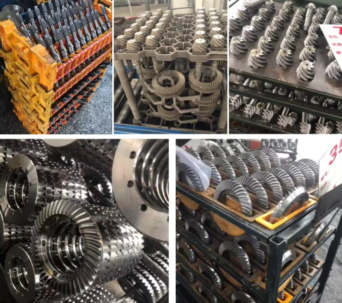
Price Comparison: Hypoid vs Spiral Bevel Gears (AUD)
Module 4 equivalent pairs, single-unit purchase. Hypoid premium reflects machine setting complexity and matched pair lapping requirement. Contact [email protected].
| Gear Type | AGMA Class | Price / Pair (AUD) | Premium Over Spiral Bevel |
|---|---|---|---|
| Spiral bevel (lapped) | 9–10 | $700–$1,400 | Base reference |
| Hypoid (industrial, lapped) | 9–10 | $900–$1,800 | +20–30% |
| Spiral bevel (ground, Cl. 11) | 11 | $1,600–$3,200 | Base Class 11 |
| Hypoid (ground, Cl. 11) | 11 | $2,200–$4,500 | +30–40% |
Hypoid Gear Lubrication: Why It Is Non-Negotiable
No other aspect of hypoid gear operation generates more field failures than incorrect lubrication — and the failure mode is rapid and destructive. When a hypoid gear pair runs with inadequate EP additive protection, the high lengthwise sliding velocity between tooth surfaces quickly overcomes the oil film, direct metal-to-metal contact occurs at the sliding zone, and adhesive wear (scuffing) strips material from the tooth flanks within hours or days of operation. The resulting damage is typically severe and irreversible — the gear set must be scrapped and replaced, not simply re-lubricated.
Hypoid gear oil specifications are not interchangeable with standard gear oil specifications. API GL-5 is the minimum classification for hypoid service. The active sulfur and phosphorus compounds in GL-5 hypoid oils react with tooth surface metal under the flash temperature conditions at the sliding contact to form a sacrificial surface layer that prevents adhesive scuffing. Standard GL-4 oils contain insufficient concentrations of these compounds for hypoid duty.
An important practical caveat: GL-5 hypoid oils are aggressive toward copper and brass components. If the gearbox housing or associated components (oil pump bushings, synchroniser rings in transmission applications) contain copper alloy parts, an EP-compatible lubricant that protects against copper corrosion must be specified — standard GL-5 can attack these materials over time. For food processing applications requiring hypoid-geometry gears (rare but occasionally specified), NSF H1-rated hypoid lubricants meeting both GL-5 EP performance and food-safe composition requirements are available from specialist lubricant formulators.
Components Specific to Hypoid Gear Assemblies
Hypoid GL-5 Gear Oil
Cannot be substituted with GL-4. Requires sulfur-phosphorus EP additives for the high lengthwise sliding contact. Use synthetic PAO GL-5 for wide-temperature-range or extended oil change applications.
Offset Shim Pack Assembly
Hypoid pinion axial position must be set to achieve both correct mounting distance and the specified shaft axis offset simultaneously — requiring more complex shimming procedure than spiral bevel assemblies.
Dual-Thrust Bearing Arrangement
Hypoid pinions generate higher axial thrust forces than equivalent spiral bevel pinions due to the combined tooth pressure angle and offset geometry. The bearing preload arrangement must be specified and set with particular care.
Preload Setting Gauge
Rolling torque measurement at the pinion during assembly confirms correct bearing preload. Hypoid pinion bearing preload is more sensitive than spiral bevel — a torque gauge is essential for correct assembly.
Customer Experiences with Hypoid Gears
“We were fitting standard GL-4 oil in what turned out to be a hypoid differential on our tipper fleet. Scuffing failures every 6 months. Ever-Power confirmed the gear type from photos, we switched to GL-5 hypoid oil — zero failures in the eighteen months since.”
“Needed to retrofit a more powerful drive into an existing conveyor gearbox housing. Ever-Power proposed a hypoid configuration that increased torque capacity by 25% within the original housing diameter. The engineering rationale was clearly explained.”
“The housing design for our conveyor drive head required an offset pinion shaft for structural reasons. Ever-Power identified that hypoid geometry was needed, designed the offset, and delivered a complete documented assembly specification.”
“Needed to reduce noise from a mixer drive in an indoor food processing facility — noise complaints from operators. Ever-Power recommended upgrading from spiral bevel to hypoid geometry which increased the contact ratio further. The noise reduction was measurable and compliance was met.”
Frequently Asked Questions: Hypoid vs Bevel Gears
Hypoid or Spiral Bevel? Our Engineers Will Advise.
Australia Ever-Power · Condell Park NSW 2200 · Custom manufacture of hypoid and spiral bevel gear sets with full technical selection support and complete documentation for Australian industry.