
Why Manufacturing Process Defines Everything About the Gear
The manufacturing process used to produce a bevel gear is not merely a production detail — it is the primary determinant of tooth profile accuracy, surface finish, contact pattern quality, and ultimately the gear’s load capacity, noise level, and service life. Two gear sets nominally identical in geometry, material, and heat treatment specification can perform radically differently in service if one was produced by form milling to AGMA Class 8 and the other by continuous generative grinding to AGMA Class 12.
Bevel gear manufacturing is substantially more complex than equivalent cylindrical gear production. The conical geometry requires either specialised dedicated bevel gear machines (Gleason face milling, Klingelnberg palloid hobbing, Oerlikon semi-completing) or carefully programmed 5-axis CNC machining centres to generate the correct tooth form. The range of available processes spans simple single-point milling suitable for small production runs of large gears, through to high-volume face-milling and lapping cycles producing automotive differential ring-and-pinion sets in under a minute per part.
Australia Ever-Power, based in Condell Park NSW 2200, applies the full range of manufacturing technologies described in this article to produce bevel gear sets across module sizes from 1 to 20+ and precision classes from AGMA 8 through to AGMA 12 for demanding applications. Understanding these processes helps engineers specify the right precision and surface quality level — without over-specifying (wasting money) or under-specifying (risking failure).
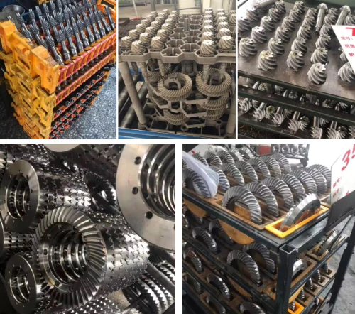
Form Milling (Formed-Disc Milling)
How It Works
Form milling uses a disc milling cutter or end mill with a profile ground to match the desired tooth cross-section. The cutter removes material from the blank one tooth space at a time — the blank is held in an indexing fixture and rotated by exactly one tooth pitch after each pass until all tooth spaces are machined. Because the cutter profile matches the tooth cross-section at a specific cone distance (typically the mean or midface point), the tooth form is theoretically accurate only at that cross-section and represents an approximation at the inner and outer ends of the face.
For straight bevel gears with face widths less than approximately 30% of the outer cone distance, this approximation error is generally acceptable. For spiral bevel gears, form milling produces a simplified approximation of the curved tooth form and is typically limited to prototyping or very small production runs where the cost of Gleason or Klingelnberg machine time cannot be justified.
Achievable Precision and Surface Quality
AGMA Quality Class 6–8 is typically achievable by form milling on a well-maintained machine with sharp tooling and careful fixturing. Surface roughness is typically Ra 1.6–3.2 µm after milling, which is adequate for straight bevel gear applications at moderate speeds but insufficient for high-speed spiral bevel applications. Subsequent gear grinding or lapping can improve both accuracy and surface finish, but the initial form milling accuracy limits the achievable final result without very substantial material removal in the finishing stage.
When to Specify Form Milling
Form milling is most appropriate for large module (8+), low-volume (1–10 parts) straight bevel gear production — replacement gears for mining equipment, custom gears for specialist machinery, and first-article prototypes. The relatively low machine investment cost and wide availability of 5-axis CNC machining centres capable of form milling makes it the accessible option for gear manufacturers without dedicated bevel gear machine investment. Australia Ever-Power uses CNC form milling for large-module custom replacement gear sets where lead time and flexibility outweigh the benefits of higher-production methods.
Face Milling — Gleason Completing & Semi-Completing
The Gleason Face Milling Concept
Gleason face milling is the dominant production method for automotive differential spiral bevel gears and is widely used for medium-to-high-volume industrial spiral bevel production. A rotating circular face mill cutter head, with cutting blades arranged around its circumference, cuts one tooth slot per cutter revolution. The cutter head and gear blank move simultaneously in a programmed generating motion that produces the correct tooth helicoid surface geometry through the combined motion of the cutter and blank — not from the cutter profile shape alone.
The Gleason completing process machines both flanks of each tooth in a single setup, while the semi-completing process finishes one flank per setup (allowing independent optimisation of convex and concave tooth flanks). Semi-completing is preferred for gears requiring precise contact pattern control or low transmission error, as it allows the tooth form to be adjusted on each flank independently to achieve the target contact pattern under operating load. Gleason machines use Tilt, Swivel, Spiral Angle, and other machine settings to precisely control the resultant tooth geometry and contact pattern — a body of knowledge codified in Gleason’s CAGE gear analysis software.
Precision and Production Rate
Gleason face milling can achieve AGMA Class 9–10 accuracy in the roughing/semi-finishing state (as-cut, before lapping). After lapping (a paired run-in process using an abrasive compound), the surface finish improves to Ra 0.4–0.8 µm and transmission error decreases substantially. Lapped Gleason gears are the standard for automotive differentials worldwide. For applications requiring higher precision (AGMA Class 11–12), gear grinding follows the roughing operation as described below.
The Lapping Process
Lapping runs the matched pinion and ring gear in mesh together in a lapping machine, using an oil-suspended abrasive compound (silicon carbide or aluminium oxide, typically 240–400 grit) that gradually removes high spots on the tooth surface. The process corrects minor profile deviations, reduces surface roughness, and optimises the contact pattern to conform closely to the intended target. The critical constraint is that lapped bevel gears are matched pairs — the abrasive wear process produces a unique mating between the specific pinion and ring gear that ran together during lapping. Mixing lapped gears from different pairs produces a mismatch that defeats the improvement lapping provided.
Continuous Hobbing — Klingelnberg Palloid Method
The Klingelnberg palloid hobbing process uses a conical hob (a spiral cutting tool with tapered geometry) rotating in continuous generating motion to produce spiral bevel gear teeth on a blank that simultaneously rotates in the generating roll. Unlike the Gleason face mill method, the palloid process is continuous — the hob and blank rotate continuously through the cutting cycle rather than indexing one tooth at a time. This produces a different tooth form geometry: palloid gears have a constant tooth depth (no taper) and a spiral angle that is theoretically exact along the entire face width, rather than the involute-based tooth form of Gleason gears.
The most practically significant advantage of the Klingelnberg palloid system is interchangeability — because the tooth form is defined purely by the hob geometry and generating motion, any palloid-cut pinion of the correct specification can mesh correctly with any palloid-cut ring gear of the correct specification, without matched pairing. This is a substantial advantage for spare parts management: individual gears can be replaced from stock without sourcing the complete matched pair. For this reason, Klingelnberg palloid gears have found particular favour in industrial gearbox applications where inventory management is a priority.
Klingelnberg also manufactures their Cyclo-Palloid system as an evolution of the palloid method, offering both continuous generating cutting and CNC-controlled grinding cycles on the same machine platform, enabling AGMA Class 11–12 precision from a single production cell. This system is widely used in European industrial gear manufacturing for high-precision gearboxes in machine tools, printing machinery, and precision instrumentation.
Bevel Gear Grinding
The Case for Post-Hardening Grinding
Case carburising and hardening — the heat treatment that provides the high surface hardness (58–62 HRC) and tough core needed for maximum load capacity in bevel gears — inevitably introduces distortion. Thermal gradients during carburising and quenching cause the gear blank to distort: tooth spacing becomes non-uniform, the tooth profile deviates from the theoretical involute or helicoid, and the pitch line runout (eccentricity) increases. These distortions, if left uncorrected, produce elevated transmission error, noise, and dynamic overload on individual teeth.
Gear grinding after hardening corrects these distortions by removing a controlled amount of material (typically 0.05–0.2 mm per flank) from the hardened tooth surface using CBN (cubic boron nitride) or aluminium oxide grinding wheels. The result is a gear tooth that combines the surface hardness of a fully-hardened case with the profile accuracy and surface finish achievable only by abrasive finishing processes — something no soft-cutting method can achieve since hardening always follows cutting and always introduces at least some distortion.
Gleason PHOENIX and CNC Bevel Gear Grinders
Modern CNC bevel gear grinding machines (Gleason PHOENIX series, Klingelnberg Oerlikon G series) use the same generating principle as the Gleason face mill or Klingelnberg hob, but replace the cutting tool with a CBN grinding wheel. The generating motion drives the wheel across the tooth surface in the same path that the theoretical generating gear would follow, correcting both profile errors and helix angle deviations simultaneously. 5-axis CNC control allows independent correction of tooth profile errors measured by a coordinate measuring machine (CMM) or gear inspection device — a closed-loop manufacturing process that achieves repeatable AGMA Class 11–12 results.
Surface Finish and Superfinishing
Ground bevel gears achieve surface roughness values of Ra 0.4–0.8 µm, adequate for most high-performance applications. For the most demanding applications — helicopter gearboxes, racing vehicle differentials, high-speed machine tool spindles — superfinishing (also called isotropic superfinishing or REM polishing) further reduces surface roughness to Ra 0.05–0.1 µm by removing the asperities left by the grinding process through controlled vibratory processing with fine ceramic media. Superfinished bevel gears show measurable improvements in surface fatigue life, reduced friction losses, and lower operating temperatures compared to conventionally ground gears.
Near-Net-Shape Methods: Forging, Casting & Powder Metallurgy
Precision Forging
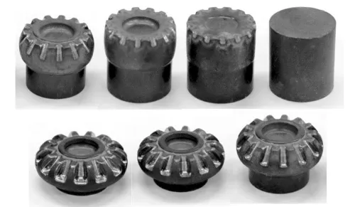
Hot precision forging of bevel gear blanks (and in some cases near-complete gear forms) is used in high-volume automotive production. Forged blanks exhibit superior grain flow alignment with the tooth profile compared to machined blanks cut from bar stock, improving fatigue strength by 15–25%. Precision forging to tight dimensional tolerances reduces the amount of material removed in subsequent machining, lowering material waste and total production cost per part. Some automotive differential ring gears are forged to within 0.3–0.5 mm of final tooth profile before hardening and finish machining.
Die Casting and Investment Casting
Straight bevel gears in bronze, aluminium, and zinc alloy are produced by die casting or sand casting for low-load, low-speed applications in instruments, hand tools, and general machinery. Cast gears can be used without additional machining for AGMA Class 5–6 applications, or with tooth grinding for higher precision. Investment casting (lost-wax process) achieves tighter dimensional tolerances suitable for small stainless steel bevel gears in food processing and medical equipment applications where corrosion resistance and moderate precision are the primary requirements.
Powder Metallurgy
Powder metal (PM) bevel gears are produced by compacting metal powder in a precision die, then sintering in a furnace to achieve the final density and strength. PM gears achieve AGMA Class 5–7 accuracy directly from the press, with further improvement possible by coining (pressing after sintering) or machining. PM is most cost-effective for high-volume production of small-to-medium bevel gears in consumer products, power tools, and light machinery where the low per-part cost (no machining waste, automated pressing) outweighs the lower density and porosity limitations compared to wrought steel gears.
Manufacturing Method Comparison Table
Summary of key technical and commercial characteristics by production method. AGMA precision class is for the as-finished gear surface condition.
| Process | AGMA Class | Surface Ra | Vol. Suitability | Interchangeable? | Best Application |
|---|---|---|---|---|---|
| Form Milling (CNC) | 6–8 | 1.6–3.2 µm | 1–50 parts | Yes | Large custom, mining replacement |
| Gleason Face Mill + Lap | 9–10 | 0.4–0.8 µm | 500–50,000+ | Paired only | Automotive differential, industrial |
| Klingelnberg Palloid | 9–10 | 0.8–1.6 µm | 50–5,000 | Yes | Industrial gearboxes, spares stock |
| CNC Gear Grinding | 11–13 | 0.2–0.4 µm | 1–500 | Yes | Aerospace, medical, precision |
| Superfinished Ground | 12–13 | 0.05–0.1 µm | 1–200 | Yes | Helicopters, F1, precision drives |
| Precision Forging | Blank only | N/A (pre-machine) | 5,000+ | Post-process | Automotive OEM, blank quality |
| Powder Metallurgy | 5–7 | 1.6–3.2 µm | 10,000+ | Yes | Consumer goods, power tools |
Materials and Heat Treatment in the Manufacturing Sequence
Case Carburising and Hardening
The standard heat treatment sequence for high-performance bevel gears is: rough machining → normalising or stress relief → finish machining (soft cutting) → case carburising → gas quenching → tempering → gear grinding (or lapping). Case carburising diffuses carbon into the outer 0.8–2.0 mm of the tooth surface from a gas or liquid carbon-rich atmosphere at 900–950°C, creating a surface with 0.7–0.9% carbon content while the core remains at the original 0.15–0.20% carbon of the gear steel alloy. After quenching and tempering, surface hardness reaches 58–62 HRC while the core retains 35–45 HRC toughness — the combination essential for tooth bending strength and surface durability simultaneously.
Through-Hardening and Nitriding Alternatives
Through-hardened bevel gears (typically from steel grades 4140 or 4340, hardened to 32–38 HRC throughout) are used in moderate-duty applications where case-hardening cost cannot be justified. The lower surface hardness limits contact fatigue resistance but simplifies manufacturing since through-hardened gears require minimal distortion correction by grinding. Gas or plasma nitriding (producing a surface hardness of 58–65 HRC at a much shallower case depth of 0.1–0.4 mm) provides excellent surface durability with minimal distortion, making it suitable for large gears where carburising distortion would be prohibitive and grinding stock removal would compromise the thin nitride case.
Non-Ferrous Materials
Bronze alloy bevel gears (typically leaded tin bronze or manganese bronze) are produced by casting and turning, or by form milling from bar stock. They are not heat-treated but rely on the inherent hardness (120–200 HV) and self-lubricating properties of the bronze alloy. They find use in low-load, low-speed applications where corrosion resistance, non-sparking properties, or the ability to operate with marginal lubrication are important. Stainless steel bevel gears for food processing and marine applications are typically machined from grade 316 bar and either left as-cut or lightly surface-hardened by nitriding where load capacity permits.
Ever-Power Manufacturing Flow: From Order to Delivery
Customer provides drawings, samples, or existing gear specifications. Our engineering team reviews for completeness, clarifies ambiguities, and proposes manufacturing method, material, and heat treatment recommendations based on application requirements.
Blank material is sourced from certified stock, cut to size, and rough-turned to the conical blank profile. Stress relief or normalising is performed on larger blanks before finish machining to eliminate internal stresses from prior hot-working.
Tooth slots are generated by the selected cutting method. First-off inspection confirms tooth form, tooth spacing, face width, and contact pattern against specification before series production proceeds.
Case carburising, through hardening, or nitriding per specification. Hardness verification on witness samples accompanies each batch. Furnace cycle records are retained for material traceability documentation.
Post-hardening finishing to achieve the specified precision class and surface quality. Lapping is applied to matched pairs; grinding produces individually corrected interchangeable gears. Contact pattern and backlash are verified on a testing machine under the specified mounting conditions.
100% dimensional inspection on critical parameters, surface finish verification, material certificate review, and preparation of the inspection report and documentation package. Gears are protected with VCI corrosion inhibitor packaging and dispatched with full identification and traceability records.
Manufacturing Cost Versus Precision — Price Comparison
Indicative pricing comparison (AUD) for equivalent module 4 spiral bevel gear pair by production method. Volume: 1 pair. Contact [email protected] for current project-specific quotations.
| Manufacturing Route | AGMA Class | Est. Price / Pair | Lead Time |
|---|---|---|---|
| Form milled, as-cut, through-hardened | 7–8 | AUD $320–$580 | 2–4 wks |
| Form milled, case-carburised, lapped pair | 9–10 | AUD $700–$1,200 | 3–5 wks |
| Face-milled, case-carburised, CNC ground | 11 | AUD $1,500–$3,000 | 4–7 wks |
| CNC ground, case-carburised, superfinished | 12–13 | AUD $4,000–$9,000+ | 6–12 wks |
Australia Ever-Power Manufacturing Advantages
Compared to importing gear sets from offshore catalogue suppliers or purchasing through agents without manufacturing capability, sourcing directly from Australia Ever-Power provides specific, measurable advantages for Australian industrial customers:
Engineering support from our Condell Park NSW team with no time zone delays, no language barriers, and direct access to the people making your gears — not a customer service intermediary quoting catalogue stock.
Non-standard modules, uncommon tooth counts, special shaft angles, custom materials — all producible. Catalogue suppliers decline these orders; we engage with them as our primary value-add capability.
Material certificates, heat treatment records, dimensional inspection reports, and hardness test results accompany every order on request — essential for mining, defence, and safety-critical applications where documentation is a compliance requirement.
For equipment downtime situations, we offer expedited manufacturing slots for critical replacement gear sets. Offshore suppliers typically quote 8–16 weeks; we regularly deliver urgent custom gear sets in 2–4 weeks for Australian customers.
Customer Experiences with Our Manufacturing
“We needed a straight bevel pair in module 8 with a non-standard 16-tooth pinion and 48-tooth ring gear for a cement plant mixer. Most suppliers wouldn’t quote without an MOQ. Ever-Power delivered a single pair in 3 weeks, correctly hardened and documented.”
“The ground spiral bevel set for our test machine gearbox met AGMA Class 11 on first delivery, with a complete inspection report. Offshore suppliers we’d tried previously consistently failed the precision class specification. Ever-Power’s quality is in a different league.”
“The explanation of the Gleason face-milling vs form-milling cost trade-off helped us decide on the right production route for our 200-pair annual requirement. We chose face-milling with lapping — exactly what the application needed at a competitive price.”
“For our wind turbine yaw drive gear replacement, we required full material certification to international standards for an insurance audit. Ever-Power provided the complete traceability package that our OEM could not supply for the original parts. Outstanding documentation.”
Frequently Asked Questions: Bevel Gear Manufacturing
What is the most common manufacturing method for automotive bevel gears?
What AGMA precision class do I need for my application?
Why must lapped bevel gears be replaced as matched pairs?
Can CNC machining centres replace dedicated bevel gear cutting machines?
What is the difference between lapping and gear grinding in post-machining finishing?
How does heat treatment distortion affect gear precision, and how is it managed?
What materials are used for food-grade bevel gears?
Is powder metallurgy suitable for industrial bevel gears?
How long does it take to manufacture a custom bevel gear pair in Australia?
What documentation comes with gears manufactured by Australia Ever-Power?
Custom Bevel Gear Manufacturing — Australia Ever-Power
From single custom replacements to production runs, from AGMA Class 8 through to precision-ground Class 12 — our Condell Park NSW team handles the full manufacturing spectrum with complete technical documentation.