
96–99%
Transmission Efficiency
35°
Typical Spiral Angle
1.8–2.2
Face Contact Ratio
100+
Years in Production
Contents
02 — Why Bevel Gears at All?
03 — Straight vs Spiral: The Key Differences
04 — Five Reasons Spiral Bevel Gears Win
05 — The Hypoid Variant: A Closer Look
06 — Tooth Geometry & Contact Mechanics
07 — Materials in Automotive Differentials
08 — Lubrication: Why GL-5 Is Non-Negotiable
09 — Manufacturing for Automotive Scale
10 — Electric Vehicles: Still Relevant?
11 — Spiral Bevel Gears Beyond the Car
12 — Differential Maintenance & Replacement
13 — Australia Ever-Power Supply
14 — FAQ
01
What Is an Automotive Differential — and What Does It Actually Do?
Before understanding why spiral bevel gears are the gear of choice inside a differential, it is worth being precise about what a differential does and why its mechanical demands are so specific. The automotive differential is the component within the drivetrain that allows the two driven wheels on the same axle to rotate at different speeds while still receiving torque from the engine. This capability is not optional — it is mechanically essential for any vehicle that must turn.
When a vehicle corners, the outer wheel describes a larger arc than the inner wheel and must therefore travel a greater distance in the same time. If both driven wheels were rigidly connected to a single shaft — as in the earliest motor vehicles — one wheel would be forced to skip or drag during every turn, causing tyre scrub, loss of traction, and severe mechanical stress. The differential resolves this conflict elegantly: it allows the wheel speeds to diverge while maintaining continuous torque delivery to both wheels.
A conventional open differential achieves this through a set of bevel gears: a ring gear receiving drive from the propeller shaft (via a pinion), two side gears splined to the driven axle shafts, and two or four pinion gears (spider gears) that float between the side gears and allow them to rotate at different speeds. The entire assembly is housed within a differential carrier that rotates with the ring gear. When both wheels encounter equal resistance, the pinion gears do not rotate on their own axes — they simply carry the side gears around at the same speed. When one wheel encounters less resistance than the other, the pinion gears begin to rotate, allowing the side gears to diverge in speed.
This beautifully simple mechanism — essentially unchanged in concept since Onésiphore Pecqueur patented the differential in 1828 — is what places bevel gears at the absolute centre of automotive drivetrain engineering. Every ring gear, every pinion, every spider gear in a conventional differential is a bevel gear. Understanding why spiral bevel gears were adopted for this role — and why they remain dominant over a century later — requires looking closely at the mechanical demands of the differential environment.
02
Why Bevel Gears at All? The Geometry Argument
The first question is not why spiral bevel gears specifically, but why bevel gears as a class are the correct transmission form for the differential application. The answer lies in geometry and the mechanical function of the differential itself.
The differential must transmit torque through two direction changes: first, from the longitudinal propeller shaft to the transverse axle shafts (a 90-degree change of direction), and second, within the differential cage, between the spider pinions and the side gears (also at 90 degrees or close to it). Both of these direction changes involve intersecting shaft axes, which is the defining use case for bevel gears. No other standard gear type — spur, helical, worm — can achieve an efficient right-angle drive between shafts whose axes genuinely intersect.
Worm gears, the main alternative for right-angle drives, could theoretically be used for the ring gear and pinion drive, but their efficiency at high speeds drops to 70–90%, compared to 96–99% for spiral bevel gears. In a vehicle producing 150 kW at the wheels, a 5% efficiency loss at the differential translates to 7.5 kW of waste heat — a significant fuel economy and thermal management penalty paid at every moment of vehicle operation. At the volumes and duty cycles of automotive drivetrains, this efficiency gap is commercially unacceptable.
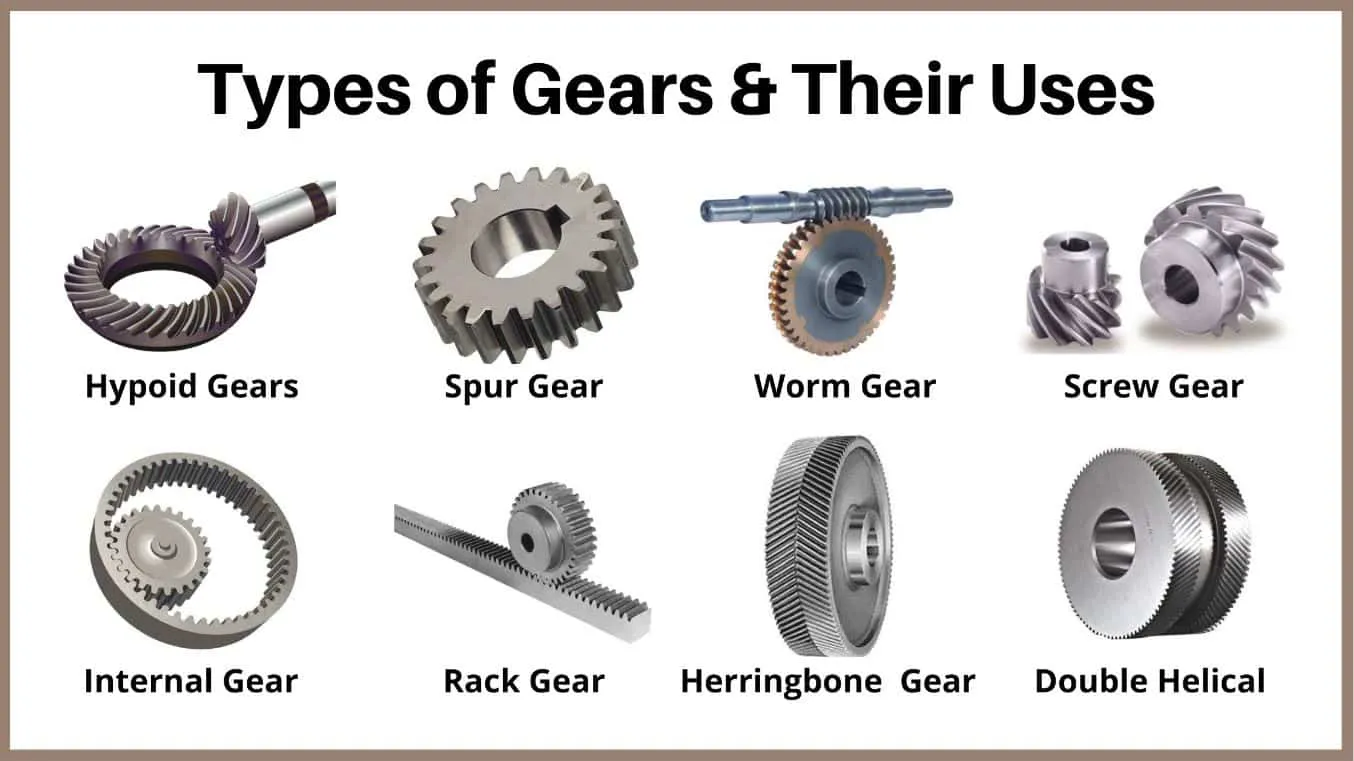
Hypoid gears — which are a sub-variant of spiral bevel gears — are actually the most common configuration in modern car rear axle differentials. Their shaft axes do not intersect, providing a packaging advantage. But they share the curved-tooth geometry of spiral bevel gears and are manufactured by the same processes, making them part of the same engineering family. The discussion of why spiral bevel gears dominate the differential therefore encompasses hypoid gears as well, and both are addressed fully in this article.
03
Straight Bevel vs Spiral Bevel — Head-to-Head in the Differential Environment
Early automotive differentials — from the 1890s through the 1920s — actually did use straight bevel gears for the ring-and-pinion drive. The shift to spiral bevel gears (and later hypoid gears) was driven by the harsh realities of higher vehicle speeds, increased engine power, and the intolerance of car occupants for drivetrain noise. Understanding the comparison between the two forms illuminates precisely why spiral bevel gears became the standard.
| Parameter | Straight Bevel Gear | Spiral Bevel Gear ✓ |
|---|---|---|
| Tooth contact type | Line contact — abrupt, full-width | Progressive elliptical contact |
| Face contact ratio | ~1.0–1.2 | 1.8–2.2 (more teeth share load) |
| Operating noise | High — pronounced gear whine above 30 km/h | Significantly lower — accepted by automotive NVH standards |
| Load capacity (same size) | Lower — single tooth pair carries full load | Higher — load shared across multiple teeth |
| Dynamic load factor | Higher — impact at every tooth engagement | Lower — gradual engagement reduces impact |
| Fatigue life | Shorter — higher peak contact stress | Longer — distributed stress, better surface durability |
| Axial thrust load | Minimal — simple bearing arrangement | Significant — requires tapered roller bearings |
| Manufacturing complexity | Lower | Higher — but well-established at automotive scale |
| Cost (automotive volumes) | Lower unit cost | Competitive — volume production has equalised costs |
| Use in modern car differentials | Rare — legacy only | Universal standard — ring-and-pinion and spider gears |
The historical transition away from straight bevel gears in automotive differentials accelerated through the 1920s and 1930s as vehicle speeds rose. At 20 km/h, a straight bevel differential might generate acceptable noise. At 80 km/h — a routine cruise speed by the 1930s — the gear mesh frequency of a straight bevel ring-and-pinion set fell squarely within the frequency range most audible and irritating to human occupants, and the differential whine became a defining quality defect of budget vehicles.
Spiral bevel gears, with their overlapping progressive tooth engagement, shift the dominant noise energy to higher harmonics and dramatically reduce the amplitude of the fundamental gear mesh frequency. Practically, this means a spiral bevel differential in a 1940s family car was noticeably quieter at highway speed than a straight bevel differential in an equivalent vehicle — a quality difference that consumers could perceive directly and that manufacturers translated into product differentiation.
04
Five Engineering Reasons Spiral Bevel Gears Became the Automotive Standard
The adoption of spiral bevel gears in the automotive differential was not driven by a single advantage but by a convergence of five independent engineering benefits, each of which addressed a specific limitation of straight bevel gears as vehicle performance expectations rose. Together, they make an overwhelming technical case.
05
The Hypoid Variant — Why Modern Cars Use a Specific Subtype
What Makes a Hypoid Gear Different from a Spiral Bevel Gear
The term “spiral bevel gear” is sometimes used loosely to encompass hypoid gears in automotive contexts, but strictly speaking they are distinct designs. In a true spiral bevel gear set, the axes of the ring gear and pinion intersect at the apex of both pitch cones. In a hypoid gear set, the pinion axis is offset above or below the ring gear axis — the axes are non-intersecting and non-parallel (skew axes). This offset — typically 30 to 50 mm in passenger car applications — is the defining geometric distinction.
The offset was introduced by Packard and Gleason in the early 1920s with a specific goal: lowering the propeller shaft. By offsetting the pinion below the ring gear centreline, the entire prop shaft can be positioned lower in the vehicle, reducing the height of the transmission tunnel hump in the passenger compartment floor. This was a meaningful comfort and styling benefit in the closed-body vehicles becoming standard through the 1920s and 1930s, and the hypoid configuration has remained universal in rear-axle passenger car differentials ever since.
The Engineering Trade-off: Sliding Contact and EP Lubrication
The pinion axis offset introduces a geometrically necessary longitudinal sliding component between the hypoid gear and pinion teeth during meshing — a sliding motion that does not exist to the same degree in pure spiral bevel gears. This sliding motion generates significantly higher contact pressures and tooth surface temperatures than occur in spiral bevel gear mesh, because the sliding velocity and the contact pressure act simultaneously. Standard gear oils, whose additive packages were designed for rolling contact between parallel-axis gears, cannot form an adequate protective film under these conditions — tooth scuffing (adhesive wear) results within minutes of operation without appropriate lubrication.
The development of extreme-pressure (EP) gear lubricants — containing sulphur-phosphorus additive packages that react at elevated surface temperatures to form a protective sulphide or phosphate reaction layer on the tooth surface — was a technological prerequisite for the success of the hypoid differential. API GL-5 and GL-6 lubricant ratings define the minimum EP performance required for hypoid gear applications, and these ratings are not interchangeable with the GL-4 ratings appropriate for spiral bevel gears without an offset. Using the wrong lubricant grade in a hypoid differential is one of the most common causes of differential failure in service.
Hypoid vs Spiral Bevel: When Each Is Used in Modern Vehicles
In the modern automotive landscape, hypoid gear differentials are essentially universal in rear-wheel-drive passenger cars and light commercial vehicles. Four-wheel-drive transfer cases and front axle differentials more commonly use spiral bevel gear sets without offset, since packaging constraints there do not demand the floor height advantage that the hypoid offset provides. Heavy commercial vehicle drive axles and off-highway equipment may use either form depending on the specific packaging and torque requirements. The spider gears and side gears within the differential cage — the components that actually provide the speed differentiation function — are almost always straight bevel or spiral bevel gears regardless of the ring-and-pinion configuration, because these components operate at very low relative speeds and the noise advantage of spiral teeth is less critical at this location.
06
Tooth Geometry and Contact Mechanics — The Physics Behind the Performance
The Hertzian Contact Ellipse
When two curved surfaces are pressed together under load, the contact region is not a point or a line but a small ellipse — described by Hertz contact theory. In a spiral bevel gear, the curved tooth surface profile in both the profile and lead directions means the contact ellipse is genuinely elliptical, with finite dimensions in both directions. This distributed contact spreads the applied load over a finite area, reducing the peak contact pressure (Hertzian stress) compared to the line contact of a straight bevel gear at the same applied force.
The contact ellipse position and shape on the tooth surface is one of the most critical parameters in spiral bevel gear design and manufacturing. A correctly positioned ellipse — centred on the mid-face of the tooth, slightly below the pitch line on the drive flank — indicates correct mesh geometry and produces uniform load distribution across the tooth. Under increasing load, the ellipse grows in size due to elastic deflection of teeth, shafts, and bearings — a phenomenon deliberately factored into the design so that at operating load, the ellipse covers approximately 60–70% of the tooth face without running off the edge. Running the ellipse off the tooth edge (toe or heel contact) causes severe stress concentration and rapid failure — this is why contact pattern verification with marking compound is non-negotiable during differential assembly and after any gear replacement.
The Gleason System in Automotive Practice
Virtually all automotive spiral bevel and hypoid differential gear sets produced in North America, Japan, Australia, and much of Asia are manufactured to the Gleason system — a standardised tooth geometry framework developed by the Gleason Corporation and its cutting machine platforms (face-milling and face-hobbing). The Gleason system defines the relationship between cutter geometry, machine settings, and resulting tooth form, and provides a complete set of design standards for spiral and hypoid bevel gears including tooth proportions, spiral angle (standardised at 35 degrees for most automotive applications), and the calculation of machine settings for any given tooth count and ratio combination.
The universality of the Gleason system in the global automotive supply chain has a practical implication for replacement parts: a Gleason-system ring gear can only be correctly meshed with a Gleason-system pinion. European-manufactured vehicles occasionally use Klingelnberg (palloid) system gears, which are geometrically incompatible with Gleason gears. Confirming the cutting system of the original gear set is an essential first step when sourcing differential gear set replacements for any vehicle, particularly for older or less-common makes.
Backlash and Its Role in Differential Noise
Backlash — the circumferential clearance between mating gear teeth when one tooth flank is in contact — is a necessary feature of all gear drives to allow for thermal expansion, lubrication film space, and manufacturing tolerance accumulation. In automotive differentials, backlash is carefully controlled during assembly using shim stacks to set the mounting distance and cone distance of ring gear and pinion. Too little backlash causes the gears to run tight, generating heat and risking scuffing under full load. Too much backlash causes a characteristic clunking sound during torque reversals — the “clunk” felt during the transition from drive to overrun. Correct backlash setting, combined with correct contact pattern verification, is the two-parameter quality check that defines a properly assembled differential.
07
Materials in Automotive Differential Gear Sets
The material specification for automotive differential spiral bevel gears has been substantially standardised by the demands of the application and the requirements of automotive OEM material specifications. The following represents the established material engineering for this application.
Ring Gear — AISI 8620 / 9310
Nickel-chromium-molybdenum (or nickel-chromium) alloy steels. Case-carburised to a case depth of 0.8–1.5 mm, oil or press-quenched, tempered at 160–180°C. Surface hardness 58–62 HRC, core hardness 32–38 HRC. The ring gear, being the larger of the two mating components, is typically manufactured from AISI 8620 in high-volume passenger car applications, with AISI 9310 reserved for performance, truck, and military applications requiring higher core toughness.
Pinion — AISI 9310 / 8822
The pinion is almost universally manufactured from a higher-alloy steel than the ring gear, even in the same differential. Because the pinion has fewer teeth and completes more rotational cycles per kilometre than the ring gear, its teeth accumulate fatigue cycles faster. AISI 9310 provides higher core toughness and case hardenability than 8620, making it the standard pinion material in passenger car and light truck differentials. Aircraft and high-performance applications use vacuum-arc-remelted (VAR) AISI 9310 for maximum cleanliness and fatigue performance.
Spider/Side Gears — AISI 8620 / 4140
The bevel spider gears and side gears within the differential cage operate at very low relative sliding speeds in normal straight-line driving and only rotate on their own axes during cornering or wheel slip events. This less severe duty cycle allows the use of AISI 8620 or 4140, case-hardened or through-hardened, at a quality grade appropriate for their lower speed and load duty. High-performance limited-slip differentials may upgrade these gears to AISI 9310 to withstand the sustained torque loading that occurs during active slip control.
Surface Treatments & Coatings
Beyond basic case hardening, automotive ring-and-pinion gears may receive shot peening of the tooth root area (to induce compressive residual stresses that improve bending fatigue resistance), phosphate coating (manganese phosphate) for run-in friction reduction and mild corrosion protection, and in some performance applications, physical vapour deposition (PVD) coatings such as DLC (diamond-like carbon) for scuffing resistance in marginal lubrication conditions during engine start.
08
Lubrication — Why GL-5 Is Non-Negotiable in Hypoid Differentials
The lubrication of an automotive differential is not a simple matter of “put some gear oil in.” The chemistry of the lubricant must be precisely matched to the contact mechanics of the gear type. This distinction is critical for anyone maintaining, repairing, or replacing differential gear sets.
The sulphur-phosphorus EP additives in GL-5 oils work by reacting chemically with the metal surface at the high temperatures generated by the sliding contact in the hypoid mesh zone, forming a sacrificial iron sulphide or iron phosphate layer that prevents direct metal-to-metal contact even when the hydrodynamic oil film momentarily collapses. This reaction-layer protection mechanism is why the lubricant chemistry must be correct — a mechanical oil film alone cannot protect hypoid gear surfaces under the combination of high sliding velocity and high contact pressure present during hard acceleration or high-load sustained driving.
Modern synthetic gear oils (PAO-based) rated GL-5 offer substantially better performance than traditional mineral-oil GL-5 products across the temperature range encountered in Australian conditions — from cold overnight temperatures in alpine Victoria to the extreme heat of a summer day in the Pilbara or central Queensland. Synthetic lubricants maintain adequate viscosity at low temperatures (preventing cold-start damage) while providing better high-temperature viscosity retention and oxidative stability than mineral oils. For vehicles operating in Australian climate extremes or used for towing — which elevates differential temperatures significantly — synthetic GL-5 is the recommended lubricant irrespective of the original factory specification, which may predate synthetic lubricant availability.
One critical caution: GL-5-rated gear oils are NOT appropriate for use in manual gearboxes where synchroniser cones are made of brass or bronze. The sulphur EP additives in GL-5 oils are aggressive toward yellow metals and will corrode and destroy brass synchroniser rings. The differential oil fill and the gearbox oil fill are completely separate systems in rear-wheel-drive vehicles and must be treated as such. This confusion is a surprisingly common maintenance error.
09
Manufacturing Spiral Bevel Differential Gears at Automotive Scale
The production of automotive differential spiral bevel gear sets is one of the most refined gear manufacturing processes in existence — refined by decades of volume production and quality pressure from automotive OEM customers. The production sequence below describes the standard process for a passenger car ring-and-pinion set.
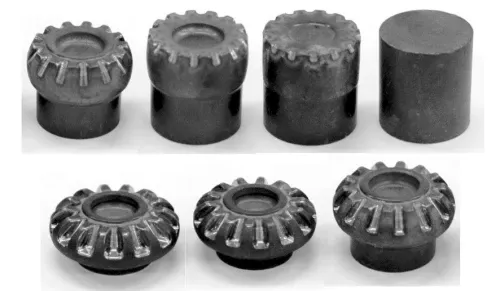
Steel Billet & Forging
Clean alloy steel billets (AISI 9310 or 8620) are forged to rough gear blank shape. Forging refines grain structure and aligns grain flow with the final tooth geometry, improving fatigue resistance over bar-stock blanks. Normalising heat treatment relieves forging stresses.
CNC Turning & Drilling
The blank is turned to final cone profile, bore, and back face geometry, leaving stock for post-heat-treatment grinding. For ring gears, the bolt hole circle and flange features are machined to drawing. Concentricity of bore to pitch cone establishes the datum for all subsequent operations.
Face Milling / Face Hobbing
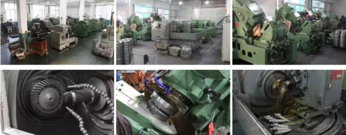
The critical gear tooth cutting operation, performed on Gleason-type bevel gear cutting machines (e.g. Gleason 245HC, Phoenix series). Face milling produces one tooth slot per indexing cycle (batch method); face hobbing produces teeth in continuous rotation. High-production automotive lines prefer face hobbing for throughput. Carbide-insert face-mill cutters must be maintained to exacting tolerances for consistent tooth geometry.
Carburising & Press Quenching
Batch or continuous furnace carburising at 920–950°C in a controlled carbon atmosphere for 4–12 hours depending on required case depth. Press quenching — in which the hot gear is quenched while clamped in a die — controls distortion during hardening to minimise post-quench grinding stock. Surface hardness 58–62 HRC; tempering at 160–180°C stabilises the martensite. 100% hardness check at tooth surface and core.
Hard Finishing — Lapping
Automotive differential gears are typically finish-processed by gear lapping — running the matched ring and pinion together in mesh under light load with a fine abrasive compound. Lapping corrects minor tooth geometry errors from heat treatment distortion, refines the tooth surface finish (Ra typically 0.2–0.4 µm), and establishes the final matched contact pattern between the specific ring gear and pinion pair. Lapped pairs must never be separated and reassembled with different partners.
CMM Inspection & Matching
Every gear undergoes CMM dimensional verification. Matched pairs are assigned a composite backlash code that is stamped on both components, enabling the assembler to set correct backlash using the corresponding shim thickness. Noise testing on a roll-test machine (measuring transmission error and sidebanding around the gear mesh frequency) may be performed on sampled pairs to verify NVH performance before shipping.
10
Electric Vehicles — Do Spiral Bevel Gears Still Matter?
A reasonable question as battery electric vehicles (BEVs) grow to represent an increasing share of global vehicle production: does the transition to electric drive eliminate the need for spiral bevel differentials? The answer is nuanced, and it is not a simple “yes, spiral bevel gears are obsolete in EVs.”
Single-Motor EVs: The Differential Persists
Most current battery EVs use a single electric motor per driven axle, connected to the driven wheels through a fixed-ratio single-speed reduction gearbox and — in most cases — a conventional open differential or a torque-vectoring limited-slip differential. The differential still performs the same function it performs in an ICE vehicle: allowing wheel speed differentiation during cornering. The ring-and-pinion remains a spiral bevel (or helical) gear set. As long as a single motor drives two wheels on the same axle, a differential mechanism is required, and bevel gears remain relevant.
Dual-Motor EVs: Differential Function Replaced by Software
In dual-motor EV configurations — where each driven wheel has its own electric motor (or each axle has its own motor with no mechanical differential between the wheels) — the wheel speed differentiation function is achieved electronically by independently controlling the speed of each motor. In these architectures, the mechanical differential assembly is eliminated, and with it the ring-and-pinion bevel gear set. Leading EV performance vehicles using this architecture have no spiral bevel differential in the traditional sense.
The Industrial and Replacement Market: Unchanged
Even as EV penetration grows in new vehicle sales, the existing global fleet of hundreds of millions of ICE vehicles with conventional differentials will continue to require maintenance and replacement gear sets for decades. In Australia — where the working fleet includes vast numbers of rear-wheel-drive utes, commercial vehicles, off-highway equipment, and agricultural machinery — demand for spiral bevel differential gear sets in the replacement market will remain substantial well past 2040. Australia Ever-Power’s supply and engineering support for this market reflects this long-term demand outlook.
Beyond the automotive differential, spiral bevel gears are entirely unaffected by the EV transition in the vast majority of their applications — industrial gearboxes, mining equipment, aerospace drives, agricultural machinery, marine propulsion, and robotics all continue to rely on spiral bevel gears without any automotive-driven disruption. The bevel gear market is significantly broader than the automotive differential, and the automotive differential itself is not disappearing as a product category — it is evolving.
11
Spiral Bevel Gears Beyond the Automotive Differential
The same properties that make spiral bevel gears the dominant choice in automotive differentials — quiet operation, high load capacity in a compact envelope, long fatigue life, and high efficiency — make them the preferred gear type in a wide range of demanding applications across other sectors. The following examples illustrate this breadth.
✈️ Helicopter Tail Rotor Drives
The tail rotor gearbox on a helicopter must redirect drive from the main rotor shaft (or its reduction stage) to the tail rotor shaft at 90 degrees, at very high speed and with the minimum possible weight and noise. Precision-ground spiral bevel gears manufactured from VAR AISI 9310 to AGMA 13+ quality are the universal standard. Failure of this component has catastrophic consequences, making material quality and manufacturing precision absolute priorities.
🏭 Industrial Right-Angle Gearboxes
Right-angle bevel gear reducers for conveyor drives, mixer drives, and pump drives across mining, food processing, and manufacturing industries all use spiral bevel gear sets for the input right-angle stage. The efficiency advantage over worm gear reducers at these power levels (typically 15–500 kW) translates to meaningful energy savings across multi-shift industrial operations.
🚢 Marine Z-Drive Propulsion
Azimuth thruster and Z-drive systems on ships and offshore support vessels use spiral bevel gear stages to redirect drive from the vertical motor shaft to the horizontal propeller shaft. Corrosion-resistant alloy steel gears running in sealed gearboxes with synthetic marine gear oil deliver the long service life between dry-dock maintenance intervals demanded in commercial marine operations.
⛏️ Mining Shearer Drives
Longwall coal shearer cutting heads receive drive power through a series of bevel gear stages that redirect the horizontal motor shaft output to the rotating cutting drum. These gears transmit hundreds of kilowatts in an extremely compact housing subject to water, coal dust, shock loading, and vibration. Heavy-duty spiral bevel gears in wide-face, large-module configurations are the only viable solution at these power densities.
🤖 Robotic Wrist Articulation
The wrist axis of a 6-axis industrial robot must redirect drive at 90 degrees in an extremely compact, lightweight package while maintaining the positioning accuracy that modern robotic welding, assembly, and painting applications demand. Zerol or precision-ground spiral bevel gears at AGMA 12–13 quality, with controlled low backlash, are the standard solution in robot wrist joint designs from all major manufacturers.
🌾 Agricultural PTO Gearboxes
Combine harvester header drives, rotary tiller gearboxes, and mower conditioner drives all use bevel gear stages to redirect PTO power from the horizontal tractor shaft to working components oriented at various angles. While straight bevel gears are used in lower-speed, lower-cost agricultural applications, spiral bevel gears are increasingly specified for premium agricultural equipment where noise, efficiency, and durability are competitive differentiators.
12
Differential Maintenance, Failure Diagnosis, and Gear Replacement
Recognising the Warning Signs
Differential gear failure rarely occurs without warning. The characteristic symptoms, in approximate order of severity, are: a persistent whine or howl from the rear of the vehicle that varies with speed (not engine speed); a regular clunking sound during acceleration or deceleration; a rumbling noise during cornering; play or looseness felt in the drivetrain during torque reversal; and in advanced failure, vibration through the vehicle floor or a pronounced grinding sound under load. Any of these symptoms warrants immediate inspection — operating a vehicle with a failing differential can result in complete drivetrain seizure and loss of vehicle control.
Common Causes of Differential Gear Failure
Lubricant Failure
The most common failure cause. Lubricant leakage (from failed pinion seal), incorrect lubricant specification (GL-4 in a GL-5 application), overextended oil change intervals in towing or off-road use, or water contamination. Without adequate lubricant film, scuffing and surface fatigue accelerate dramatically.
Incorrect Contact Pattern
Replacing only the pinion or ring gear without re-establishing the correct contact pattern; incorrect shim setting during assembly; worn or damaged carrier bearings that allow the ring gear to deflect away from the pinion under load. All result in stress concentration at the tooth edge rather than the tooth face centre.
Overloading
Modified vehicles with significantly increased engine power whose differential gear set was specified for the original lower power level; sustained heavy towing that exceeds the differential’s rated torque; off-road use with sudden full-lock articulation that induces extreme spider gear loading. Service factor application is absent in most consumer vehicle maintenance decisions.
Excessive Backlash
Worn carrier bearings allow the ring gear to migrate away from the pinion, increasing backlash beyond the design tolerance. The resulting clunk under torque reversal indicates impact loading at tooth contact — a symptom that should be addressed before it causes tooth fatigue failure.
Replacement Best Practices
When replacing differential gear sets, the following practices are non-negotiable for a successful outcome: replace ring gear and pinion as a matched pair; replace all carrier bearings and pinion bearings at the same time; replace the pinion seal; use a new shim set calibrated to set correct backlash and preload for the new bearings; and verify the contact pattern with marking compound before the assembly is closed. Cutting corners on any of these steps typically results in a repeat failure within a fraction of the normal service life.
For Australian operators requiring replacement spiral bevel differential gear sets — whether for passenger vehicles, commercial vehicles, or industrial equipment differentials — Australia Ever-Power supplies matched pairs with full material certification from Condell Park NSW. Contact [email protected] with the vehicle make, model, and year, or the gear set dimensions if the application is industrial equipment.
13
Australia Ever-Power — Spiral Bevel Gear Supply for Automotive and Industrial Applications
Australia Ever-Power operates from Condell Park NSW and supplies the full range of spiral bevel gear types — ring-and-pinion differential sets, industrial right-angle gear pairs, spider and side gear sets, miter gear pairs, and custom gear sets to customer drawings — across Australia and the Asia-Pacific region. Our supply model combines competitive AUD pricing with genuine technical engineering support, full material documentation, and Australian lead times that overseas-only suppliers cannot match.
📦
Standard Stock
Standard module, pressure angle, and tooth count combinations available from stock for common industrial applications. Fast dispatch from Condell Park NSW to any Australian address.
✏️
Custom to Drawing
Non-standard specifications produced to customer-supplied engineering drawings. First-article inspection report and material certificates provided with the first production batch. Lead time typically 2–4 weeks.
🔬
Reverse Engineering
Legacy or undocumented gear sets measured on CMM from a sample. Manufacturing drawing derived from measured data. Suitable for replacement of obsolete or non-catalogued differential gear sets in older equipment.
🛠️
Application Engineering
Technical review of gear type selection, material specification, and quality grade for new designs. Contact pattern guidance for installations and replacements. Lubrication specification advice for specific applications and Australian environmental conditions.
Featured Product
Spiral Miter Bevel Gear — 1:1 High-Performance Direction Change
Precision spiral miter bevel gear pairs for food processing, robotic, and automation right-angle drives requiring 1:1 ratio, low noise, and high efficiency in a compact envelope.
14
Frequently Asked Questions
Common questions about spiral bevel gears, hypoid differentials, and automotive drivetrain gear sets — answered by Australia Ever-Power’s engineering team.